Nissan Note E12. Manual - part 401


  Index      Nissan     Nissan Note E12 - Service and Repair Manual


Search            


Content   ..  399  400  401  402   ..


Nissan Note E12. Manual - part 401


INT-26

< REMOVAL AND INSTALLATION >

FLOOR TRIM

6. Disconnect negative and positive battery terminals, then wait at least three minutes. Refer to 

PG-69,

"Removal and Installation (Battery)"

.

WARNING:

Before servicing the SRS, turn the ignition switch off, disconnect both battery terminals then wait

at least three minutes.

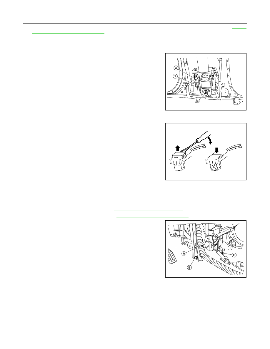
7. Disconnect the harness connector (A) from the seat belt retrac-

tor (1).

WARNING:

• Do not drop the seat belt retractor. Always handle it with

care.

• Always point pretensioner cylinder away from body when

handling.

CAUTION:

• For removing/installing the shoulder belt pre-tensioner

harness connector, insert a thin screwdriver wrapped in

tape into the notch, then lift the lock and remove the har-

ness connector as shown.

• Install the harness connector with the lock raised, and

push the lock into the harness connector as shown.

• After installing the harness connector, check that the lock

is pushed in securely.

8. Remove seat belt lower anchor bolt.

CAUTION:

Before removing the seat belt lower anchor bolt, note the positions of washers and spacers for

correct installation. 

9. Remove diagnosis sensor unit. Refer to 

SR-21, "Removal and Installation"

.

10. Remove shift selector. Refer to  (5MT) or 

TM-227, "Removal and Installation"

 (CVT)

11. Remove A/C unit assembly bolt (C) and bracket (1) from vehicle.
12. Remove instrument panel lower bracket bolt (B) and screw (A)

and reposition bracket as necessary to remove floor trim.

ALHIA0316ZZ

PHIA0953J

ALJIA0712ZZ

FLOOR TRIM

INT-27

< REMOVAL AND INSTALLATION >

C

D

E

F

G

H

I

K

L

M

A

B

INT

N

O

P

13. Release carpet hook clips with a suitable tool (A) and remove.

: Clip

14. Release pawls using a suitable tool (A) and open the harness

clips.

: Pawl

15. Remove floor trim.

INSTALLATION

Installation is in the reverse order of removal.

CAUTION:

• Replace harness protector B with a new part after removal. Do not reuse harness protector B.

AWJIA0736ZZ

AWJIA0737ZZ

INT-28

< REMOVAL AND INSTALLATION >

HEADLINING

HEADLINING

Exploded View

INFOID:0000000009016050

1. Headlining

2. Rear assist grip (RH)

3. Front assist grip (RH)

4. Microphone (if equipped)

5. Sun visor holder (RH)

6. Sun visor holder (LH)

7. Map lamp (if equipped)

8. Sun visor (RH)

9. Sun visor (LH)

10. Interior room lamp

11. Rear assist grip (LH)

A. Headlining clip

Pawl

AWJIA1143ZZ

HEADLINING

INT-29

< REMOVAL AND INSTALLATION >

C

D

E

F

G

H

I

K

L

M

A

B

INT

N

O

P

Removal and Installation

INFOID:0000000009016051

REMOVAL

1. Remove front pillar finishers (LH/RH). Refer to 

INT-19, "FRONT PILLAR FINISHER : Removal and Instal-

lation"

.

2. Remove sun visor screws and sun visorS (LH/RH). 
3. Remove map lamp (if equipped). Refer to 

INL-37, "Removal and Installation"

.

4. Remove interior room lamp. Refer to 

INL-39, "Removal and Installation"

.

5. Remove microphone (if equipped). Refer to 

AV-101, "Removal and Installation"

.

6. Remove center pillar upper finishers (LH/RH). Refer to 

INT-23, "CENTER PILLAR UPPER FINISHER :

Removal and Installation"

.

7. Remove luggage side upper finishers (LH/RH). Refer to 

INT-33, "LUGGAGE SIDE UPPER FINISHER :

Removal and Installation"

.

8. Insert a suitable tool (A) at approximately a 30 degree angle into

the sun visor holder notch on the front of the sun visor holder (1)

and press in the locking tab (B) to release it. While holding in

lock tab (B), rotate the sun visor holder (1) 90 degrees to release

it from the headlining.

: Front

CAUTION:

Do not force the sun visor holder when removing as the

locking tab may be damaged if the suitable tool is not posi-

tioned correctly.

NOTE:

If the sun visor holder (1) does not fully rotate, make sure that

the suitable tool (A) is pressing in on the locking tab (B) and is

not positioned under locking tab (B). Reinsert the suitable tool

(A) as necessary to release the locking tab (B).

9. Release assist grip pawls and remove bolt (A) using a suitable

tool and remove all assist grips.

:Pawl

10. Remove headlining clips.
11. Remove headlining through the back door.

CAUTION:

• Do not reuse headlining. 

INSTALLATION

Installation is in the reverse order of removal.

CAUTION:

• Remove all remaining adhesive from roof panel.

• Do not reuse headlining. Replace with new part after removal.

ALJIA0537ZZ

AWJIA1126ZZ


Content   ..  399  400  401  402   ..