Nissan Note E12. Manual - part 232
P1564 ASCD STEERING SWITCH
EC-267
< DTC/CIRCUIT DIAGNOSIS >
[HR16DE]
C
D
E
F
G
H
I
J
K
L
M
A
EC
N
P
O
2. Also check harness for short to ground and short to power.
Is the inspection result normal?
YES
>> GO TO 7.
NO
>> GO TO 6.
6.
DETECT MALFUNCTIONING PART
Check the following.
• Combination switch (spiral cable)
• Harness for open and short between ECM and combination switch
>> Repair open circuit, short to ground or short to power in harness or connectors.
7.
CHECK ASCD STEERING SWITCH
EC-267, "Component Inspection"
Is the inspection result normal?
YES
>> GO TO 8.
NO
>> Replace ASCD steering switch.
8.
CHECK INTERMITTENT INCIDENT
GI-41, "Intermittent Incident"
.
>> INSPECTION END
Component Inspection
INFOID:0000000009418252
1.
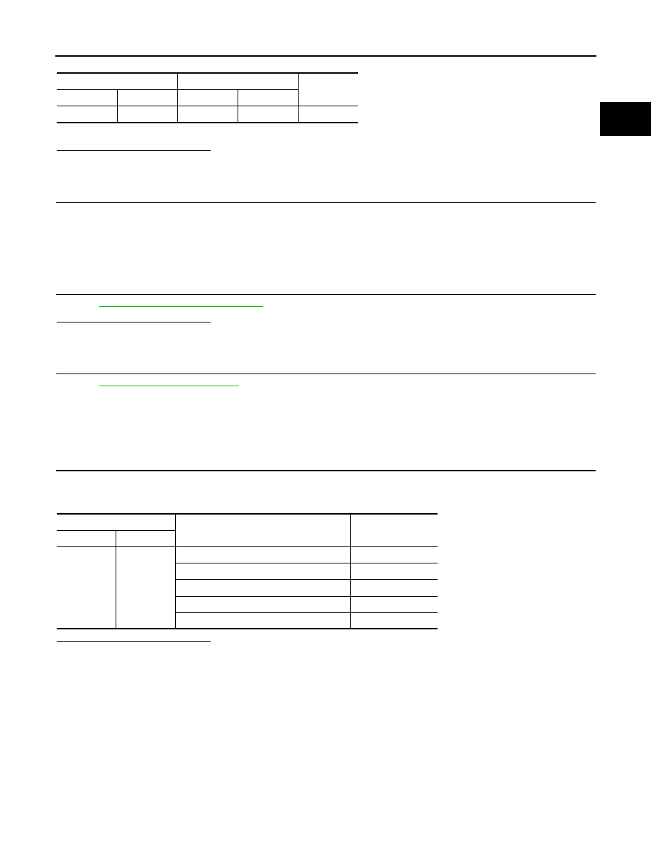
CHECK ASCD STEERING SWITCH
Check resistance between combination switch (spiral cable) harness connector terminals under the following
conditions.
Is the inspection result normal?
YES
>> INSPECTION END
NO
>> Replace ASCD steering switch.
Combination switch
ECM
Continuity
Connector
Terminal
Connector
Terminal
M88
13
E16
94
Existed
Combination switch
Condition
Resistance (
Ω)
Connector
Terminals
M88
13 and 16
MAIN switch: Pressed
Approx. 0
CANCEL switch: Pressed
Approx. 250
COAST/SET switch: Pressed
Approx. 660
ACCEL/RES switch: Pressed
Approx. 1,480
All ASCD steering switches: Released
Approx. 4,000