Nissan Note E12. Manual - part 229
P0850 PNP SWITCH
EC-255
< DTC/CIRCUIT DIAGNOSIS >
[HR16DE]
C
D
E
F
G
H
I
J
K
L
M
A
EC
N
P
O
4. Check 1st trip DTC.
Is 1st trip DTC detected?
YES
>> Proceed to
.
NO
>> INSPECTION END
5.
PERFORM COMPONENT FUNCTION CHECK
Perform component function check. Refer to
EC-255, "Component Function Check"
.
NOTE:
Use component function check the overall function of the park/neutral position (PNP) signal circuit. During this
check, a 1st trip DTC might not be confirmed.
Is the inspection result normal?
YES
>> INSPECTION END
NO
>> Proceed to
.
Component Function Check
INFOID:0000000009022604
1.
PERFORM COMPONENT FUNCTION CHECK
1. Turn ignition switch ON.
2. Check the voltage between ECM harness connector and ground.
Is the inspection result normal?
YES
>> INSPECTION END
NO
>> Proceed to
.
Diagnosis Procedure
INFOID:0000000009022605
1.
CHECK TRANSMISSION RANGE SWITCH (CVT) OR PARK/NEUTRAL POSITION (PNP) SWITCH (M/T)
POWER SUPPLY CIRCUIT
1. Turn ignition switch OFF.
2. Disconnect transmission range switch (CVT) or PNP switch (M/T) harness connector.
3. Turn ignition switch ON.
4. Check the voltage between transmission range switch (CVT) or PNP switch (M/T) harness connector and
ground.
Is the inspection result normal?
YES
>> GO TO 3.
ENG SPEED
1,500 - 6,375 rpm
COOLAN TEMP/S
More than 70
°C (158°F)
B/FUEL SCHDL
4 (CVT) or 2.75 (M/T) - 31.8 msec
VHCL SPEED SE
More than 64 km/h (40 mph)
Shift lever
Suitable position
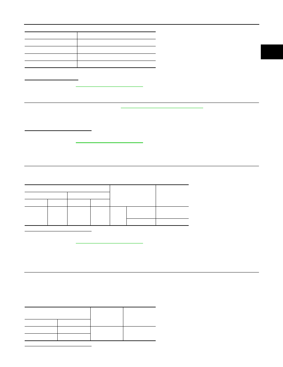
ECM
Condition
Voltage
+
−
Connector
Terminal
Connector
Terminal
F11
69
(PNP
signal)
E16
108
Shift
lever
P or N (CVT)
Neutral (M/T)
Battery voltage
Except above
Approx. 0 V
Transmission range switch (CVT) /
PNP switch (M/T)
Ground
Voltage
Connector
Terminal
F52 (CVT)
7
Ground
Battery voltage
F24 (M/T)
2