Nissan Note E12. Manual - part 165


  Index      Nissan     Nissan Note E12 - Service and Repair Manual


Search            


Content   ..  163  164  165  166   ..


Nissan Note E12. Manual - part 165


DLK-164

< REMOVAL AND INSTALLATION >

REMOTE KEYLESS ENTRY RECEIVER

REMOTE KEYLESS ENTRY RECEIVER

Removal and Installation

INFOID:0000000009567390
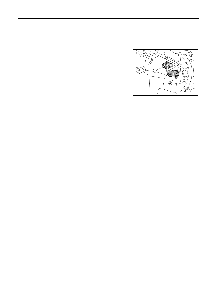
REMOVAL

1. Remove glove box assembly. Refer to 

IP-25, "Removal and Installation"

.

2. Remove remote keyless entry receiver bolt (A).
3. Disconnect the harness connector and remove remote keyless

entry receiver (1)

INSTALLATION

Installation is in the reverse order of removal.

JMKIA7947ZZ

INTELLIGENT KEY BATTERY

DLK-165

< REMOVAL AND INSTALLATION >

C

D

E

F

G

H

I

J

L

M

A

B

DLK

N

O

P

INTELLIGENT KEY BATTERY

Removal and Installation

INFOID:0000000009567391

1. Release the lock knob at the back of the Intelligent Key and remove the mechanical key.

2. Insert a suitable tool (A) wrapped with a cloth into the slit of the

corner and rotate it to separate the upper part from the lower

part.

CAUTION:

• Do not touch the circuit board or battery terminal.

• The key fob is water-resistant. However, if it does get wet,

immediately wipe it dry. 

3. Replace the battery with new one.

4. Align the tips of the upper and lower parts, and then push them

together until it is securely closed.

CAUTION:

• When replacing battery, keep dirt, grease, and other for-

eign materials off the electrode contact area.

• After replacing the battery, check that all Intelligent Key

functions work normally.

PIIB6221E

Battery replacement

:Coin-type lithium battery 
(CR2025)

PIIB6222E

EC-1

ENGINE

C

D

E

F

G

H

I

J

K

L

M

SECTION 

EC

A

EC

N

O

P

CONTENTS

ENGINE CONTROL SYSTEM

HR16DE

PRECAUTION ...............................................

6

PRECAUTIONS ...................................................

6

Precaution for Supplemental Restraint System 
(SRS) "AIR BAG" and "SEAT BELT PRE-TEN-
SIONER" .................................................................
..

6

On Board Diagnostic (OBD) System of Engine 
and CVT  ..................................................................
..

6

General Precautions  .................................................

7

PREPARATION ...........................................

10

PREPARATION ..................................................

10

Special Service Tools ..............................................

10

SYSTEM DESCRIPTION  .............................

11

COMPONENT PARTS  .......................................

11

ENGINE CONTROL SYSTEM ...................................

11

ENGINE CONTROL SYSTEM : 
Component Parts Location ....................................

11

ECM ........................................................................

15

Accelerator Pedal Position Sensor ..........................

15

Air Fuel Ratio Sensor 1  ...........................................

15

Air Fuel Ratio Sensor 1 Heater  ...............................

15

ASCD Steering Switch  ............................................

16

Camshaft Position Sensor (PHASE)  .......................

16

Clutch Pedal Position Switch  ..................................

16

Cooling Fan .............................................................

16

Crankshaft Position Sensor (POS) ..........................

17

Electric Throttle Control Actuator  ............................

17

Engine Coolant Temperature Sensor ......................

17

Engine Oil Pressure Sensor ....................................

18

Engine Oil Temperature Sensor ..............................

18

EVAP Canister Purge Volume Control Solenoid 
Valve .......................................................................

18

Exhaust Valve Timing Control Position Sensor .......

19

Exhaust Valve Timing Control Solenoid Valve ........

19

Fuel Injector  ............................................................

19

Fuel Pump  ...............................................................

19

Heated Oxygen Sensor 2  ........................................

20

Heated Oxygen Sensor 2 Heater  ............................

20

Ignition Coil With Power Transistor  .........................

20

Intake Air Temperature Sensor  ...............................

21

Intake Valve Timing Control Solenoid Valve  ...........

21

Knock Sensor  ..........................................................

21

Mass Air Flow Sensor ..............................................

22

Refrigerant Pressure Sensor  ...................................

22

Stop Lamp Switch & Brake Pedal Position Switch ....

22

Throttle Control Motor ..............................................

22

Throttle Control Motor Relay  ...................................

22

Throttle Position Sensor  ..........................................

23

WARNING LAMPS/INDICATOR LAMPS ..................

23

WARNING LAMPS/INDICATOR LAMPS : Engine 
Oil Pressure Warning Lamp ....................................

23

WARNING LAMPS/INDICATOR LAMPS : Mal-
function Indicator Lamp (MIL) ..................................

24

STRUCTURE AND OPERATION  .....................

26

Positive Crankcase Ventilation  ................................

26

SYSTEM ............................................................

27

ENGINE CONTROL SYSTEM  ...................................

27

ENGINE CONTROL SYSTEM : System Descrip-
tion ...........................................................................

27

ENGINE CONTROL SYSTEM : Fail Safe  ..............

28

MULTIPORT FUEL INJECTION SYSTEM  ................

29

MULTIPORT FUEL INJECTION SYSTEM : Sys-
tem Description ........................................................

30

ELECTRIC IGNITION SYSTEM .................................

32

ELECTRIC IGNITION SYSTEM : System De-
scription ...................................................................

32

AIR CONDITIONING CUT CONTROL .......................

33

AIR CONDITIONING CUT CONTROL : System 
Description ...............................................................

33

AUTOMATIC SPEED CONTROL DEVICE (ASCD) ....

33

EC-2

AUTOMATIC SPEED CONTROL DEVICE (AS-
CD) : System Description  ......................................
.

34

CAN COMMUNICATION ...........................................

34

CAN COMMUNICATION : System Description  ......

34

COOLING FAN CONTROL .......................................

34

COOLING FAN CONTROL : System Description ...

35

EVAPORATIVE EMISSION SYSTEM .......................

35

EVAPORATIVE EMISSION SYSTEM : System 
Description .............................................................
.

36

INTAKE VALVE TIMING CONTROL  ........................

36

INTAKE VALVE TIMING CONTROL : System De-
scription .................................................................
.

37

EXHAUST VALVE TIMING CONTROL  ....................

37

EXHAUST VALVE TIMING CONTROL : System 
Description .............................................................
.

38

ENGINE PROTECTION CONTROL AT LOW EN-
GINE OIL PRESSURE  .............................................
.

38

ENGINE PROTECTION CONTROL AT LOW EN-
GINE OIL PRESSURE : System Description  ........
.

38

WARNING/INDICATOR/CHIME LIST .......................

39

WARNING/INDICATOR/CHIME LIST : Warning 
lamps/Indicator lamps ............................................
.

39

OPERATION ......................................................

40

AUTOMATIC SPEED CONTROL DEVICE (ASCD) ...

40

AUTOMATIC SPEED CONTROL DEVICE (AS-
CD) : Switch Name and Function  ..........................
.

40

ON BOARD DIAGNOSTIC (OBD) SYSTEM  .....

42

Diagnosis Description  .............................................

42

GST (Generic Scan Tool)  .......................................

42

DIAGNOSIS SYSTEM (ECM)  ............................

43

DIAGNOSIS DESCRIPTION  .....................................

43

DIAGNOSIS DESCRIPTION : 1st Trip Detection 
Logic and Two Trip Detection Logic  ......................
.

43

DIAGNOSIS DESCRIPTION : DTC and Freeze 
Frame Data ............................................................
.

43

DIAGNOSIS DESCRIPTION : Counter System  .....

44

DIAGNOSIS DESCRIPTION : Driving Pattern  .......

47

DIAGNOSIS DESCRIPTION : System Readiness 
Test (SRT) Code  ...................................................
.

48

DIAGNOSIS DESCRIPTION : Malfunction Indica-
tor Lamp (MIL)  .......................................................
.

49

On Board Diagnosis Function .................................

49

CONSULT Function ................................................

53

ECU DIAGNOSIS INFORMATION ..............

62

ECM ...................................................................

62

Reference Value .....................................................

62

Fail Safe .................................................................

73

DTC Inspection Priority Chart ..............................

74

DTC Index ..............................................................

76

Test Value and Test Limit  .......................................

78

WIRING DIAGRAM  ....................................

86

ENGINE CONTROL SYSTEM ...........................

86

Wiring Diagram  .......................................................

86

BASIC INSPECTION .................................

107

DIAGNOSIS AND REPAIR WORKFLOW ........

107

Work Flow  .............................................................

107

Diagnostic Work Sheet  .........................................

109

ADDITIONAL SERVICE WHEN REPLACING 
ECM ..................................................................

111

Description ............................................................

111

Work Procedure  ....................................................

111

ACCELERATOR PEDAL RELEASED POSI-
TION LEARNING ..............................................

113

Description ............................................................

113

Work Procedure  ....................................................

113

THROTTLE VALVE CLOSED POSITION 
LEARNING .......................................................

114

Description ............................................................

114

Work Procedure  ....................................................

114

IDLE AIR VOLUME LEARNING .......................

115

Description ............................................................

115

Work Procedure  ....................................................

115

MIXTURE RATIO SELF-LEARNING VALUE 
CLEAR ..............................................................

117

Description ............................................................

117

Work Procedure  ....................................................

117

BASIC INSPECTION ........................................

118

Work Procedure  ....................................................

118

FUEL PRESSURE CHECK ..............................

122

Work Procedure  ....................................................

122

HOW TO SET SRT CODE ................................

124

Description ............................................................

124

SRT Set Driving Pattern ........................................

125

Work Procedure  ....................................................

127

DTC/CIRCUIT DIAGNOSIS .......................

129

TROUBLE DIAGNOSIS - SPECIFICATION 
VALUE ..............................................................

129

Description ............................................................

129

Component Function Check  .................................

129

Diagnosis Procedure .............................................

130

POWER SUPPLY AND GROUND CIRCUIT ....

137

Diagnosis Procedure .............................................

137

U0101 CAN COMM CIRCUIT ...........................

140

DTC Description ....................................................

140

Diagnosis Procedure .............................................

140


Content   ..  163  164  165  166   ..