Nissan Note E12. Manual - part 87
C1101, C1102, C1103, C1104 WHEEL SENSOR
BRC-39
< DTC/CIRCUIT DIAGNOSIS >
[ABS]
C
D
E
G
H
I
J
K
L
M
A
B
BRC
N
O
P
Is the inspection result normal?
YES
>> GO TO 10.
NO
>> Check the following:
• 10A fuse No. 50 located in the IPDM E/R
• Harness between ABS actuator and electric unit (control unit) and IPDM E/R
10.
CHECK ABS ACTUATOR AND ELECTRIC UNIT (CONTROL UNIT) GROUND CIRCUIT
1. Turn ignition switch OFF.
2. Check continuity between ABS actuator and electric unit (control unit) connector E33 terminals and
ground.
Is the inspection result normal?
YES
>> GO TO 11.
NO
>> Repair or replace malfunctioning components.
11.
CHECK WHEEL SENSOR INPUT VOLTAGE
1. Connect ABS actuator and electric unit (control unit) connector E33.
2. Turn ignition switch ON.
3. Check voltage between suspect wheel sensor harness connector terminals.
Is the inspection result normal?
YES
>> Replace wheel sensor. Refer to
BRC-69, "FRONT WHEEL SENSOR : Removal and Installation"
or
BRC-70, "REAR WHEEL SENSOR : Removal and Installation"
. Then, GO TO 12.
NO
>> Replace ABS actuator and electric unit (control unit). Refer to
BRC-73, "Removal and Installa-
.
12.
CONFIRM REPAIR
With CONSULT
1. Clear all DTCs.
2. Perform DTC confirmation procedure. Refer to
.
Does DTC C1105, C1106, C1107 or C1108 reset?
YES
>> Replace ABS actuator and electric unit (control unit). Refer to
BRC-73, "Removal and Installa-
.
NO
>> Inspection End.
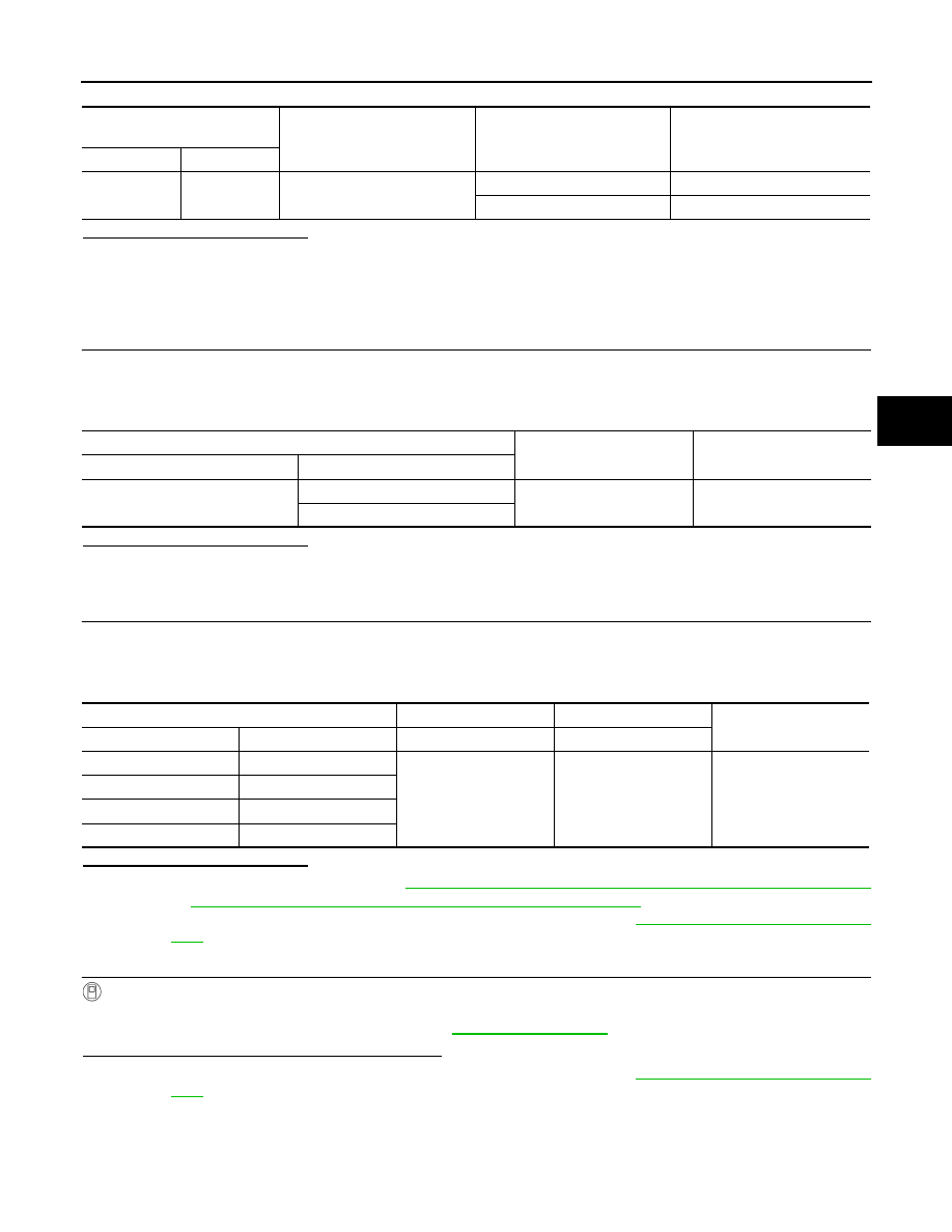
ABS actuator and electric unit
(control unit)
Ground
Condition
Voltage
(Approx.)
Connector
Terminal
E33
6
—
Ignition switch ON
Battery voltage
Ignition switch OFF
0V
ABS actuator and electric unit (control unit)
—
Continuity
Connector
Terminal
E33
13
Ground
Yes
38
Wheel Sensor
(+)
(-)
Voltage
(Approx.)
Wheel
Connector
Terminal
Terminal
Front LH
E51
1
2
Battery voltage
Front RH
E52
Rear LH
B22
Rear RH
B35