Nissan Leaf. Manual - part 661


  Index      Nissan     Nissan Leaf (2011-2014 year) - Service and Repair Manual


Search            


Content   ..  659  660  661  662   ..


Nissan Leaf. Manual - part 661


TURN SIGNAL LAMP CIRCUIT

EXL-245

< DTC/CIRCUIT DIAGNOSIS >

[HALOGEN HEADLAMP]

C

D

E

F

G

H

I

J

K

M

A

B

EXL

N

O

P

Is the inspection result normal?

YES

>> GO TO 3.

NO

>> GO TO 4.

3.

CHECK TURN SIGNAL LAMP OPEN CIRCUIT

1. Turn power switch OFF.

2. Disconnect BCM connector.

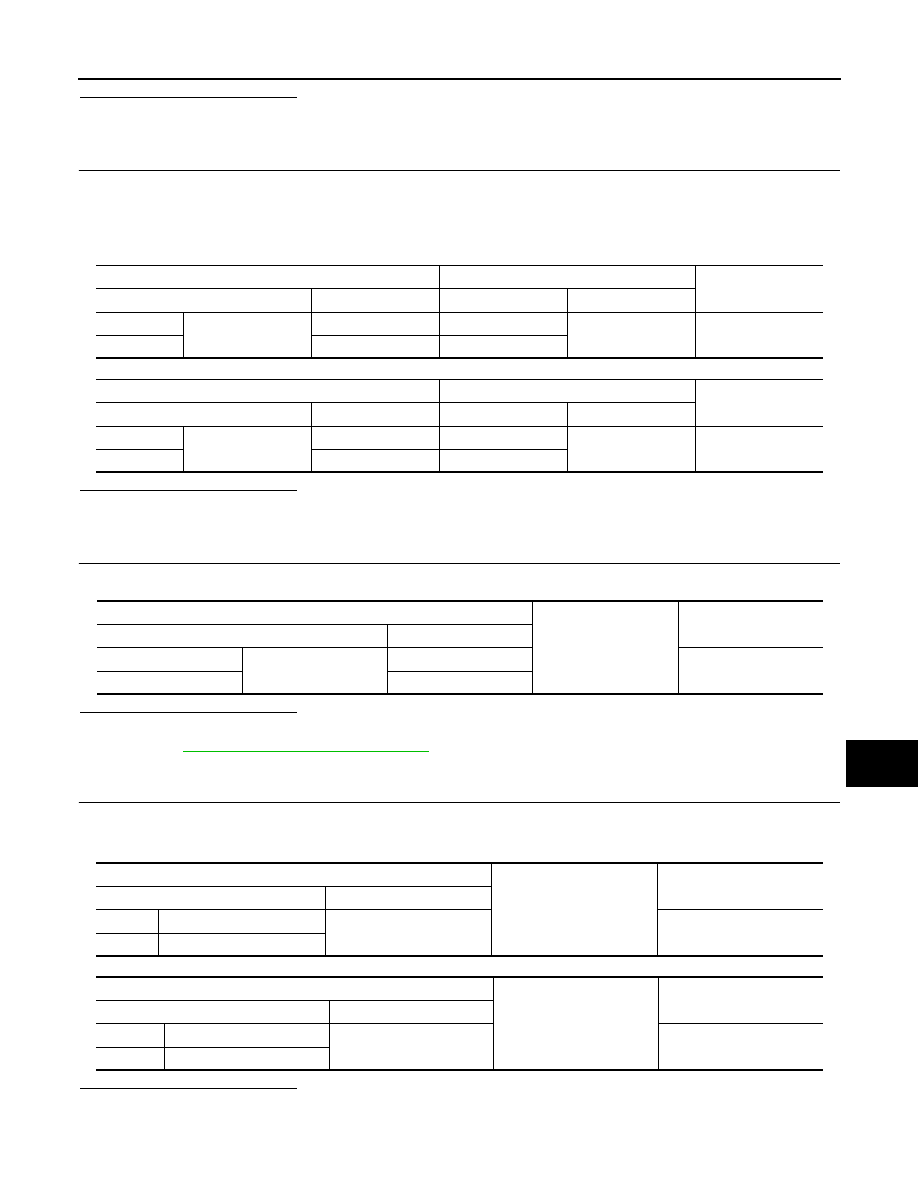
3. Check continuity between BCM harness connector and front combination lamp, side turn signal lamp or

rear combination lamp harness connector.

Front turn signal lamp

Rear turn signal lamp

Is the inspection result normal?

YES

>> GO TO 5.

NO

>> Repair or replace harness.

4.

CHECK TURN SIGNAL LAMP SHORT CIRCUIT

Check continuity between BCM harness connector and ground.

Is the inspection result normal?

YES

>> Check each bulb socket for internal short circuit, and if check result is normal, replace BCM. Refer

to 

BCS-72, "Removal and Installation"

.

NO

>> Repair or replace harness.

5.

CHECK TURN SIGNAL LAMP GROUND OPEN CIRCUIT

Check continuity between BCM harness connector and front combination lamp or rear combination lamp and

ground.

Front turn signal lamp

Rear turn signal lamp

Is the inspection result normal?

YES

>> Check corresponding bulb socket and harness. Repair or replace if necessary.

NO

>> Repair or replace harness.

BCM

Front combination lamp

Continuity

Connector

Terminal

Connector

Terminal

 RH

M25

61

E45

5

Yes

 LH

60

E26

BCM

Rear combination lamp

Continuity

Connector

Terminal

Connector

Terminal

RH

M25

61

B59

4

Yes

LH

60

B80

BCM

Ground

Continuity

Connector

Terminal

RH

M25

61

No

LH

60

Front combination lamp

Ground

Continuity

Connector

Terminal

RH

E45

3

Yes

LH

E26

Rear combination lamp

Ground

Continuity

Connector

Terminal

RH

B59

5

Yes

LH

B80

EXL-246

< DTC/CIRCUIT DIAGNOSIS >

[HALOGEN HEADLAMP]

OPTICAL SENSOR

OPTICAL SENSOR

Component Function Check

INFOID:0000000010121466

1.

CHECK OPTICAL SENSOR SIGNAL BY CONSULT

CONSULT DATA MONITOR

1. Turn power switch ON.

2. Select “OPTISEN (DTCT)” in “Data Monitor” of “BCM (HEADLAMP)”.

3. Turn lighting switch AUTO.

4. With the optical sensor illuminating, check the monitor status. 

*: Illuminates the optical sensor. The value may be less than the standard value if brightness is weak.

Is the inspection result normal?

YES

>> Optical sensor is normal.

NO

>> Refer to 

EXL-246, "Diagnosis Procedure"

.

Diagnosis Procedure

INFOID:0000000010121467

Regarding Wiring Diagram information. Refer to 

EXL-41, "Wiring Diagram"

.

1.

CHECK OPTICAL SENSOR POWER SUPPLY INPUT

1. Turn power switch ON.

2. Turn lighting switch AUTO.

3. Check voltage between optical sensor harness connector and ground.

Is the inspection result normal?

YES

>> GO TO 2.

NO

>> GO TO 4.

2.

CHECK OPTICAL SENSOR GROUND INPUT

Check voltage between optical sensor harness connector and ground.

Is the inspection result normal?

YES

>> GO TO 3.

NO

>> GO TO 6.

3.

CHECK OPTICAL SENSOR SIGNAL OUTPUT

 With illuminating the optical sensor, check voltage between optical sensor harness connector and ground.

Monitor item

Condition

Voltage (Approx.)

OPTISEN (DTCT)

Optical sensor

When illuminating

3.1 V or more *

When shutting off light

0.6 V or less

(+)

(

−)

Voltage

(Approx.)

Optical sensor

Connector

Terminal

M16

1

Ground

5 V

(+)

(

−)

Voltage

(Approx.)

Optical sensor

Connector

Terminal

M16

3

Ground

0 V

OPTICAL SENSOR

EXL-247

< DTC/CIRCUIT DIAGNOSIS >

[HALOGEN HEADLAMP]

C

D

E

F

G

H

I

J

K

M

A

B

EXL

N

O

P

*: Illuminate the optical sensor. The value may be less than the standard if brightness is weak.
Is the inspection result normal?

YES

>> GO TO 7.

NO

>> Replace the optical sensor. Refer to 

EXL-272, "Removal and Installation"

.

4.

CHECK OPTICAL SENSOR OPEN CIRCUIT

1. Turn power switch OFF.

2. Disconnect optical sensor connector and BCM connector.

3. Check continuity between optical sensor harness connector and BCM harness connector.

Is the inspection result normal?

YES

>> GO TO 5.

NO

>> Repair or replace harness.

5.

CHECK OPTICAL SENSOR SHORT CIRCUIT

Check continuity between optical sensor harness connector and ground.

Is the inspection result normal?

YES

>> Replace BCM. Refer to 

BCS-72, "Removal and Installation"

.

NO

>> Repair or replace harness.

6.

CHECK OPTICAL SENSOR GROUND OPEN CIRCUIT

1. Turn power switch OFF.

2. Disconnect optical sensor connector and BCM connector.

3. Check continuity between optical sensor harness connector and BCM harness connector.

Is the inspection result normal?

YES

>> Replace BCM. Refer to 

BCS-72, "Removal and Installation"

.

NO

>> Repair or replace harness.

7.

CHECK OPTICAL SENSOR SIGNAL OPEN CIRCUIT 

1. Turn power switch OFF.

2. Disconnect optical sensor connector and BCM connector.

3. Check continuity between optical sensor harness connector and BCM harness connector.

(+)

(

−)

Condition

Voltage

(Approx.)

Optical sensor

Connector

Terminal

M16

2

Ground

Optical sensor

When illuminating

3.1 V or more *

When shutting off light

0.6 V or less

Optical sensor

BCM

Continuity

Connector

Terminal

Connector

Terminal

M16

1

M24

17

Yes

Optical sensor

Ground

Continuity

Connector

Terminal

M16

1

No

Optical sensor

BCM

Continuity

Connector

Terminal

Connector

Terminal

M16

3

M24

18

Yes

EXL-248

< DTC/CIRCUIT DIAGNOSIS >

[HALOGEN HEADLAMP]

OPTICAL SENSOR

Is the inspection result normal?

YES

>> GO TO 8.

NO

>> Repair or replace harness.

8.

CHECK OPTICAL SENSOR SHORT CIRCUIT

Check continuity between optical sensor harness connector and ground.

Is the inspection result normal?

YES

>> Replace BCM. Refer to 

BCS-72, "Removal and Installation"

.

NO

>> Repair or replace harness.

Optical sensor

BCM

Continuity

Connector

Terminal

Connector

Terminal

M16

2

M24

14

Yes

Optical sensor

Ground

Continuity

Connector

Terminal

M16

2

No


Content   ..  659  660  661  662   ..