Nissan Primera P11. Manual - part 524


  Index      Nissan     Nissan Primera P11 (2001 year) - Service and Repair Manual


Search            


Content   ..  522  523  524  525   ..


Nissan Primera P11. Manual - part 524


25. Install mainshaft C-ring.
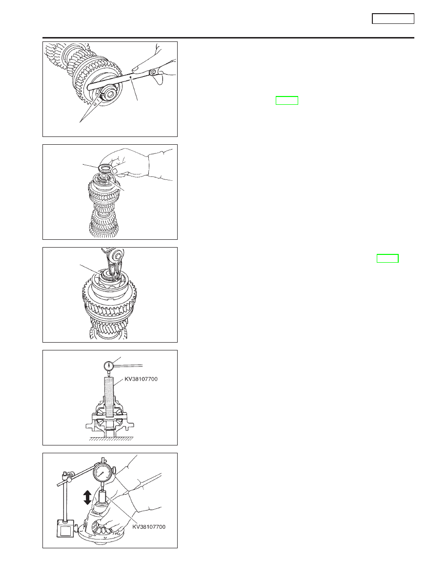
26. Using feeler gauge, measure the end play of mainshaft rear

bearing, and check if it satisfies the following specification.

End play specification:

0 - 0.06 mm (0 - 0.0024 in)

Available mainshaft C-rings:

Refer to SDS, MT-91.

27. Install C-ring holder.

28. Install snap ring.
29. Measure gear end play as a final check. Refer to, MT-63.

CAUTION:

I

Do not reuse snap ring.

Final Drive

PRE-INSPECTION

NCMT0036

I

Check the clearance between side gear and differential case
as follows.

1.

Clean final drive assembly sufficiently to prevent side gear
thrust washer, differential case, side gear, and other parts from
sticking by gear oil.

2.

Upright the differential case so that the side gear to be mea-
sured faces upward.

3.

Place final drive adapter and dial gauge onto side gear. Move
side gear up and down, and measure the clearance.

Clearance between side gear and differential case:

0.1 - 0.2 mm (0.004 - 0.008 in)

4.

If not within specification, adjust the clearance by changing
thrust washer thickness.

5.

Turn differential case upside down, and measure the clearance
between side gear and differential case on the other side in the
same way.

SMT721D

Feeler gauge

Mainshaft C-ring

SMT678D

C-ring holder

Mainshaft C-ring

SMT677D

Snap ring

SMT610AE

Dial gauge

SMT685D

REPAIR FOR COMPONENT PARTS

RS5F70A

Mainshaft and Gears (Cont’d)

MT-71

DISASSEMBLY

NCMT0016

1.

Remove mounting bolts. Then, separate the final gear from
differential case.

2.

Make a notch and remove speedometer drive gear using a
scraper or other suitable tool.

I

Bearing replacer cannot be positioned unless speedom-
eter drive gear is removed.

3.

Remove differential side bearing of final gear side.

4.

Turn differential case upside down, and remove differential
side bearing of speedometer drive gear side.

5.

Remove speedometer stopper.

6.

Remove lock pins from pinion mate shaft.

7.

Remove pinion mate shaft.

8.

Rotate pinion mate gear, and remove pinion mate gear, pinion
mate thrust washer, side gear, and side gear thrust washer
from differential case.

INSPECTION

NCMT0017

Gear, Washer, Shaft and Case

NCMT0017S01

I

Check side gear, side gear thrust washer, pinion mate shaft,
pinion mate gear, pinion mate gear washer, and differential
case.

I

Check washers for wear.

SMT609A

Chamfer

SMT840D

Puller

Puller

SMT689D

SMT839

SMT083A

REPAIR FOR COMPONENT PARTS

RS5F70A

Final Drive (Cont’d)

MT-72

Bearing

NCMT0017S04

I

Make sure bearings roll freely and are free from noise, cracks,
pitting or wear.

I

When replacing tapered roller bearing, replace outer and
inner race as a set.

ASSEMBLY

NCMT0018

1.

Apply gear oil to sliding area of differential case, each gear,
and thrust washer.

2.

Install side gear thrust washer and side gear into differential
case.

3.

Position pinion mate gear and pinion mate thrust washer
diagonally, and install them into differential case while rotating.

4.

Insert pinion mate shaft into differential case.

5.

Upright the differential case so that its side gear to be mea-
sured faces upward.

6.

Place preload adapter and dial gauge onto side gear. Move
side gear up and down, and measure the clearance.

7.

Turn differential case upside down, and measure the clearance
between side gear and differential case on the other side in the
same way.

Clearance of side gear and differential case:

0.1 - 0.2 mm (0.004 - 0.008 in)

Available differential thrust washers:

Refer to SDS, MT-92.

8.

Hammer the retaining pin into pinion mate shaft.

CAUTION:

Do not reuse retaining pin.

SPD715

SMT062A

SMT087A

SMT685D

SMT750D

REPAIR FOR COMPONENT PARTS

RS5F70A

Final Drive (Cont’d)

MT-73

9.

Align and install speedometer drive gear into differential case.

10. Install speedometer stopper.

11. Install differential side bearing.
12. Turn differential case upside down, and install another differ-

ential side bearing on the other side in the same way.

13. Install final gear into differential case. Apply sealant onto

mounting bolts, and tighten them in order as shown in the fig-
ure with specified torque.

Tightening torque:

Refer to MT-48.

Shift Control Components

INSPECTION

NCMT0019

I

Check if the width of shift fork hook (sliding area with coupling
sleeve) is within allowable specification below.

Item

One-side wear

specification

Sliding width of new part

1st & 2nd

0.2 mm (0.008 in)

7.80 - 7.93 mm

(0.3071 - 0.3122 in)

3rd & 4th

0.2 mm (0.008 in)

7.80 - 7.93 mm

(0.3071 - 0.3122 in)

5th & reverse

0.2 mm (0.008 in)

7.80 - 7.93 mm

(0.3071 - 0.3122 in)

SMT842D

Speedometer drive gear

Installation
direction

Alignment
position

SMT751D

Speedometer
drive gear

SMT752D

SMT801D

One-side wear

Sliding width of
new part

One-side wear

REPAIR FOR COMPONENT PARTS

RS5F70A

Final Drive (Cont’d)

MT-74


Content   ..  522  523  524  525   ..