Nissan Silvia. Manual - part 192
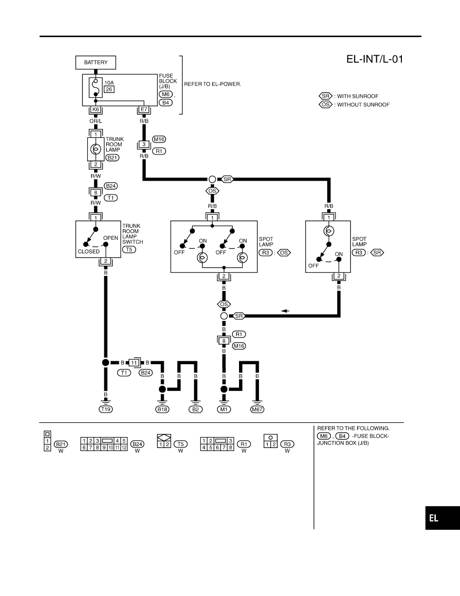
Wiring Diagram — INT/L —
NMEL0323
TEL800B
GI
MA
EM
LC
EC
FE
CL
MT
AT
PD
AX
SU
BR
ST
RS
BT
HA
SC
IDX
SPOT AND TRUNK ROOM LAMPS
Wiring Diagram — INT/L —
EL-57
|
|
|
Wiring Diagram — INT/L — NMEL0323 TEL800B GI MA EM LC EC FE CL MT AT PD AX SU BR ST RS BT HA SC IDX SPOT AND TRUNK ROOM LAMPS Wiring Diagram — INT/L — EL-57 |