Nissan Silvia. Manual - part 71


  Index      Nissan     Nissan Silvia - Service Manual (2001 year)


Search            


Content   ..  69  70  71  72   ..


Nissan Silvia. Manual - part 71


SAT994A

I

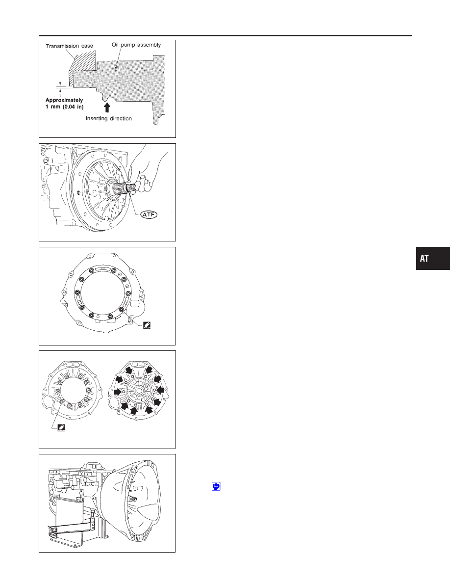
Insert oil pump assembly to the specified position in
transmission, as shown at left.

SAT114B

5.

Install O-ring on input shaft.

I

Apply ATF to O-rings.

SAT397C

6.

Install converter housing.

a.

Apply recommended sealant (Nissan genuine part: KP610-
00250 or equivalent) to outer periphery of bolt holes in con-
verter housing.

I

Do not apply too much sealant.

SAT158G

b.

Apply recommended sealant (Nissan genuine part: KP610-
00250 or equivalent) to seating surfaces of bolts that secure
front of converter housing.

c.

Install converter housing on transmission case.

SAT001B

7.

Adjust brake band.

a.

Tighten anchor end bolt to specified torque.

Anchor end bolt:

: 4 - 6 N·m (0.4 - 0.6 kg-m, 35 - 52 in-lb)

b.

Back off anchor end bolt two and a half turns.

GI

MA

EM

LC

EC

FE

CL

MT

PD

AX

SU

BR

ST

RS

BT

HA

SC

EL

IDX

ASSEMBLY

Assembly (2) (Cont’d)

AT-281

SAT002B

c.

While holding anchor end bolt, tighten lock nut.

Anchor end bolt nut:

: 41 - 50 N·m (4.1 - 5.1 kg-m, 30 - 36 ft-lb)

SAT115B

8.

Install terminal cord assembly.

a.

Install O-ring on terminal cord assembly.

I

Apply petroleum jelly to O-ring.

b.

Compress terminal cord assembly stopper and install terminal
cord assembly on transmission case.

SAT004BA

9.

Install control valve assembly.

a.

Install accumulator piston return springs B, C and D.

Free length of return springs:

Refer to SDS, AT-289.

SAT005B

b.

Install manual valve on control valve.

I

Apply ATF to manual valve.

SAT006B

c.

Place control valve assembly on transmission case. Connect
solenoid connector for upper body.

d.

Install connector clip.

ASSEMBLY

Assembly (2) (Cont’d)

AT-282

SAT353B

e.

Install control valve assembly on transmission case.

f.

Install connector tube brackets and tighten bolts A and B.

I

Check that terminal assembly does not catch.

Bolt symbol


mm (in)

A

33 (1.30)

B

45 (1.77)

SAT221B

g.

Install O-ring on oil strainer.

I

Apply petroleum jelly to O-ring.

h.

Install oil strainer on control valve.

SAT009B

i.

Securely fasten terminal harness with clips.

SAT010B

j.

Install torque converter clutch solenoid valve and A/T fluid tem-
perature sensor connectors.

GI

MA

EM

LC

EC

FE

CL

MT

PD

AX

SU

BR

ST

RS

BT

HA

SC

EL

IDX

ASSEMBLY

Assembly (2) (Cont’d)

AT-283

SAT011B

10. Install oil pan.
a.

Attach a magnet to oil pan.

SAT601B

b.

Install new oil pan gasket on transmission case.

c.

Install oil pan and bracket on transmission case.

I

Always replace oil pan bolts as they are self-sealing bolts.

I

Before installing bolts, remove traces of sealant and oil
from mating surface and thread holes.

I

Tighten four bolts in a criss-cross pattern to prevent dis-
location of gasket.

d.

Tighten drain plug.

SAT299I

11. Install PNP switch.
a.

Check that manual shaft is in “1” position.

b.

Temporarily install PNP switch on manual shaft.

c.

Move manual shaft to “N”.

SAT014B

d.

Tighten bolts while inserting 4.0 mm (0.157 in) dia. pin verti-
cally into locating holes in PNP switch and manual shaft.

SAT428DA

12. Install torque converter.
a.

Pour ATF into torque converter.

I

Approximately 2 liters (1-3/4 Imp qt) of fluid are required
for a new torque converter.

I

When reusing old torque converter, add the same amount
of fluid as was drained.

ASSEMBLY

Assembly (2) (Cont’d)

AT-284


Content   ..  69  70  71  72   ..