Nissan Silvia. Manual - part 61
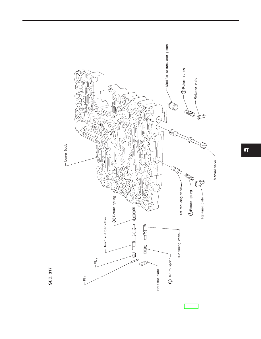
Control Valve Lower Body
COMPONENTS
NMAT0124
SAT966I
Apply ATF to all components before their installation.
Numbers preceding valve springs correspond with those shown in SDS on page AT-289.
GI
MA
EM
LC
EC
FE
CL
MT
PD
AX
SU
BR
ST
RS
BT
HA
SC
EL
IDX
REPAIR FOR COMPONENT PARTS
Control Valve Lower Body
AT-241