Nissan Almera Tino V10 (2001 year). Manual - part 184
HOW TO CHANGE SELF-DIAGNOSIS MODE WITH CONSULT-II
=NLRS0043S03
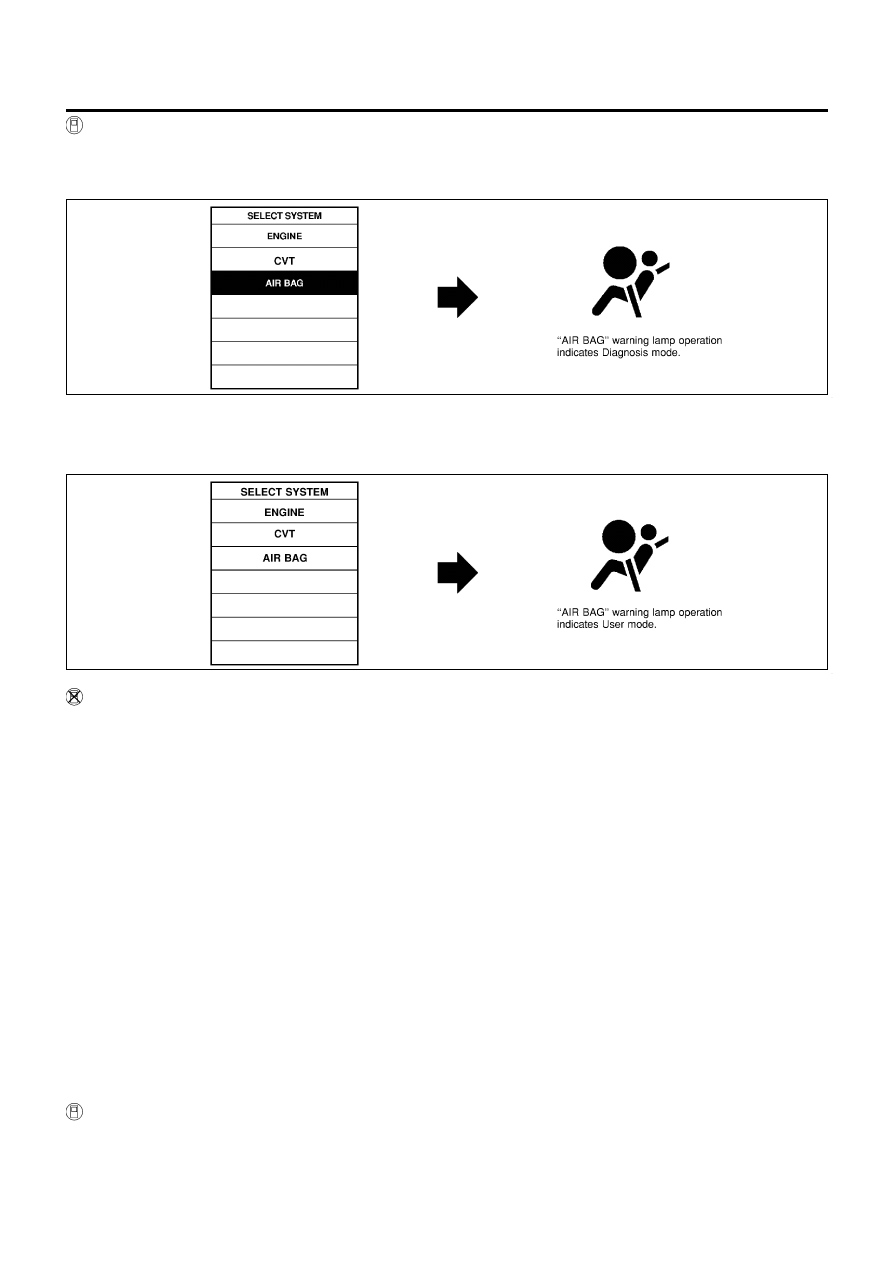
From User Mode to Diagnosis Mode
NLRS0043S0301
After selecting “AIR BAG” on the “SELECT SYSTEM” screen, User mode automatically changes to Diagno-
sis mode.
NRS115
From Diagnosis Mode to User Mode
NLRS0043S0302
To return to User mode from Diagnosis mode, touch “BACK” key of CONSULT-II until “SELECT SYSTEM”
appears, Diagnosis mode automatically changes to User mode.
NRS116
HOW TO CHANGE SELF-DIAGNOSIS MODE WITHOUT CONSULT-II
NLRS0043S04
From User Mode to Diagnosis Mode
NLRS0043S0401
When a malfunction is detected, activate the Diagnosis mode by turning the ignition switch as follows:
1) Turn ignition switch “ON”.
2) After “AIR BAG” warning lamp lights for 7 seconds, turn ignition switch “OFF” within 1 second.
3) Wait more than 3 seconds.
4) Repeat steps 1 to 3 three times.
5) Turn ignition switch “ON”.
SRS will not enter Diagnosis mode if no malfunction is detected.
From Diagnosis Mode to User Mode
NLRS0043S0402
After a malfunction is repaired, switch the ignition “OFF” for at least one second, then back “ON”. Diagnosis
mode is returned to User mode.
When a malfunction is detected, switch from Diagnosis mode to User mode by turning the ignition switch as
follows:
1) Turn ignition switch “ON”.
2) After “AIR BAG” warning lamp lights for 7 seconds, turn ignition switch “OFF” within 1 second.
3) Wait more than 3 seconds.
4) Repeat steps 1 to 3 three times.
5) Turn ignition switch “ON”.
HOW TO ERASE SELF-DIAGNOSIS RESULTS
NLRS0043S05
With CONSULT-II
NLRS0043S0501
+
“SELF-DIAG [CURRENT]”
A current Self-diagnosis result is displayed on the CONSULT-II screen in real time.
SUPPLEMENTAL RESTRAINT SYSTEM (SRS)
Trouble Diagnoses Introduction (Cont’d)
RS-38