Index Manuals Nissan Almera Tino V10 (2001 year) - Service and Repair Manual
Search copyright infringement
Content .. 180 181 182 183 ..
Nissan Almera Tino V10 (2001 year). Manual - part 182
NRS097
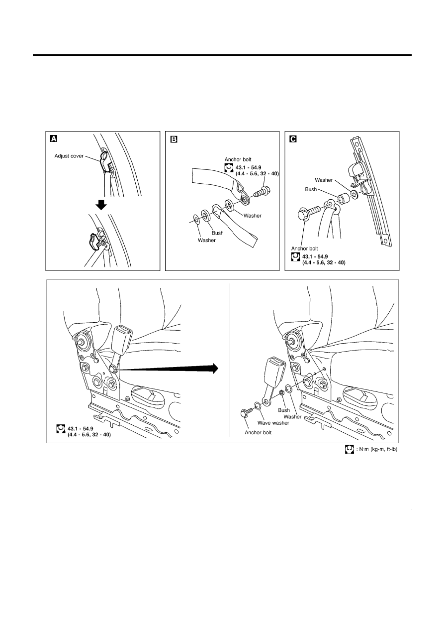
SEAT BELTS
Front Seat Belt (Cont’d)
RS-6