Nissan Almera Tino V10 (2001 year). Manual - part 180


  Index      Manuals     Nissan Almera Tino V10 (2001 year) - Service and Repair Manual


Search            copyright infringement  


Content      ..     178      179      180      181     ..


Nissan Almera Tino V10 (2001 year). Manual - part 180


SMT804BA

SMT472C

1.

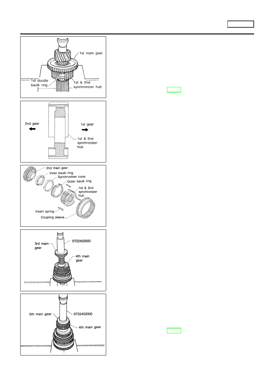
Press on 1st main gear, 1st synchronizer cone, inner & outer
baulk rings and 1st & 2nd synchronizer hub.
Refer to the illustration for step 3.

+

Pay attention to direction of 1st & 2nd synchronizer hub.

2.

Select proper snap ring of 1st & 2nd synchronizer hub to mini-
mize clearance of groove and then install it.

Allowable clearance of groove:

0 - 0.1 mm (0 - 0.004 in)

Snap ring of 1st & 2nd synchronizer hub:

Refer to SDS, MT-98.

SMT805B

3.

Install 2nd synchronizer cone, inner & outer baulk rings. Insert
springs and 1st & 2nd coupling sleeve.

4.

Install 2nd main gear.

+

Ensure four protrusions of 2nd synchronizer cone are set in
holes of 2nd main gear.

SMT600CA

5.

Press on 3rd main gear.

6.

Press on 4th main gear.

SMT473CA

7.

Press on 5th main gear.

8.

Select proper snap ring of 5th main gear to minimize clearance
of groove and then install it.

Allowable clearance of groove:

0 - 0.15 mm (0 - 0.0059 in)

Snap ring of 5th main gear:

Refer to SDS, MT-98.

REPAIR FOR COMPONENT PARTS

RS5F50A

Mainshaft and Gears (Cont’d)

MT-76

SMT059A

9.

Press on thrust washer and press on mainshaft rear bearing.

10. Press on mainshaft front bearing.
11. Measure

gear

end

play

as

a

final

check.

Refer

to

“DISASSEMBLY”, MT-73.

SMT744AA

Final Drive

DISASSEMBLY

NLMT0017

1.

Remove final gear.

2.

Remove speedometer drive gear by cutting it.

3.

Press out differential side bearings.

+

Be careful not to mix up the right and left bearings.

SMT612AA

4.

Drive out retaining pin and draw out pinion mate shaft.

5.

Remove pinion mate gears and side gears.

SMT083A

INSPECTION

NLMT0018

Gear, Washer, Shaft and Case

NLMT0018S01

+

Check mating surfaces of differential case, side gears and
pinion mate gears.

+

Check washers for wear.

SPD715

Bearings

NLMT0018S03

+

Make sure bearings roll freely and are free from noise, cracks,
pitting or wear.

+

When replacing taper roller bearing, replace outer and
inner race as a set.

REPAIR FOR COMPONENT PARTS

RS5F50A

Mainshaft and Gears (Cont’d)

MT-77

SMT062A

ASSEMBLY

NLMT0019

1.

Attach side gear thrust washers to side gears, then install pin-
ion mate washers and pinion mate gears in place.

SMT087A

2.

Insert pinion mate shaft.

+

When inserting, be careful not to damage pinion mate
thrust washers.

SMT610AH

3.

Measure clearance between side gear and differential case
with washers following the procedure below:

a.

Set Tool and dial indicator on side gear.

b.

Move side gear up and down to measure dial indicator deflec-
tion. Always measure indicator deflection on both side gears.

Clearance between side gear and differential case with
washers:

0.1 - 0.2 mm (0.004 - 0.008 in)

SMT611A

c.

If not within specification, adjust clearance by changing thick-
ness of side gear thrust washers.

Differential side gear thrust washer:

Refer to SDS, MT-98.

SMT612AA

4.

Install retaining pin.

+

Make sure that retaining pin is flush with case.

REPAIR FOR COMPONENT PARTS

RS5F50A

Final Drive (Cont’d)

MT-78

SMT609A

5.

Install final gear.

6.

Install speedometer drive gear.

SMT648

7.

Press on differential side bearings.

SMT665C

Shift Control Components

INSPECTION

NLMT0020

+

Check contact surface and sliding surface for wear, scratches,
projections or other damage.

SMT030A

Case Components

REMOVAL AND INSTALLATION

NLMT0021

Input Shaft Oil Seal

NLMT0021S01

REPAIR FOR COMPONENT PARTS

RS5F50A

Final Drive (Cont’d)

MT-79

SMT031A

+

Apply multi-purpose grease to seal lip of oil seal before
installing.

SMT034A

Mainshaft Front Bearing Outer Race

NLMT0021S02

+

Extract the oil channel and remove the mainshaft front bear-
ing outer race.

Mainshaft Rear Bearing Outer Race

NLMT0021S03

Refer to “Mainshaft Bearing Preload”, MT-99.

Differential Side Bearing Outer Race

NLMT0021S04

Refer to “Input Shaft End Play and Differential Side Bearing
Preload”, MT-99.

REPAIR FOR COMPONENT PARTS

RS5F50A

Case Components (Cont’d)

MT-80

NLMT0022

Input Shaft End Play and Differential Side
Bearing Preload

NLMT0022S01

If any of the following parts are replaced, adjust input shaft end
play.

+

Input shaft

+

Input shaft bearing

+

Clutch housing

+

Transmission case

If any of the following parts are replaced, adjust differential side
bearing preload.

+

Differential case

+

Differential side bearing

+

Clutch housing

+

Transmission case

SMT132AA

1.

Remove differential side bearing outer race (transmission case
side) and shim(s).

SMT845B

2.

Reinstall differential side bearing outer race without shim(s).

3.

Install input shaft and final drive assembly on clutch housing.

4.

Install transmission case without input shaft bearing shim(s).
Then tighten it to the specified torque.
Refer to “Case Components”, MT-62.

SMT074A

5.

Using the following procedures, measure clearance between
bearings and transmission case.

DIFFERENTIAL SIDE

NLMT0022S0101

1.

Attach dial indicator. If clamp diameter of dial indicator is too
small or too large, attach dial indicator using a magnetic stand.

ADJUSTMENT

RS5F50A

Input Shaft End Play and Differential Side Bearing Preload

MT-81

SMT075AA

2.

Insert Tool all the way into differential side gear. Move Tool up
and down and measure dial indicator deflection.

SMT076A

INPUT SHAFT SIDE

NLMT0022S0102

1.

Set dial indicator on end of input shaft.

2.

Move input shaft up and down and measure dial indicator
deflection.

3.

Select shims with proper thickness with SDS table as a guide.
Refer to SDS, MT-101.

4.

Install selected differential side bearing adjusting shim and dif-
ferential side bearing outer race.

SMT475C

5.

Check differential side bearing turning torque.

a.

Install final drive assembly on clutch housing.

b.

Install transmission case on clutch housing.

+

Tighten transmission case fixing bolts to the specified
torque. Refer to “Case Components”, MT-62.

Mainshaft Bearing Preload

NLMT0022S02

If any of the following parts are replaced, adjust mainshaft bearing
preload.

+

Mainshaft

+

Mainshaft bearings

+

Clutch housing

+

Transmission case

SMT077AA

1.

Remove mainshaft rear bearing outer race and shim(s).

ADJUSTMENT

RS5F50A

Input Shaft End Play and Differential Side Bearing Preload (Cont’d)

MT-82

SMT644AA

2.

Reinstall mainshaft rear bearing outer race without shims.

3.

Clean mating surfaces of clutch housing and transmission
case with solvent.

4.

Install mainshaft and mainshaft front bearing outer race into
transmission case. Turn mainshaft while holding bearing outer
race so that bearings are properly seated.

SMT078A

SMT079A

5.

Put straightedge [width must be more than 50 mm (1.97 in)] on
transmission case, and measure the distance from upper sur-
face of straightedge to surface of the bearing outer race using
a depth micrometer.

+

Measure at three places on bearing outer race, and take
the average.

6.

Determine dimension A to be used by the following equation.

Dimension A = Width of straightedge − measured dis-
tance

7.

Measure the distance from mating surface of clutch housing to
portion with which mainshaft front bearing outer race is to be
mated.

+

Measure at three places on the portion, and take the aver-
age.

Dimension B = Measured distance

8.

Determine dimension C to be used by the following equation.

Dimension “C” = B − A

9.

Determine total thickness of shims with SDS table as a guide.

Mainshaft bearing adjusting shim:

Refer to SDS, MT-99.

10. Install selected mainshaft bearing adjusting shim and main-

shaft bearing outer race.

11. Check total turning torque after assembly — Refer to

“ASSEMBLY”, MT-84.

ADJUSTMENT

RS5F50A

Mainshaft Bearing Preload (Cont’d)

MT-83

NLMT0093

SMT029AA

1.

Install striking lever and striking rod.

SMT645AA

2.

Install selector and retaining pin.

SMT138A

3.

Install check ball and reverse check assembly.

+

Before installation, rotate striking rod as shown in the fig-
ure to avoid interference.

SAT601C

4.

Install final drive assembly.

5.

Install input shaft and mainshaft with 1st & 2nd shift fork
assembly.

+

Be careful not to damage input shaft oil seal.

SMT065A

6.

Install interlock balls and plunger.

ASSEMBLY

RS5F50A

MT-84

SMT066A

7.

Install 3rd & 4th shift fork and bracket, then install 3rd & 4th
fork rod, stopper ring and retaining pin.
When installing stopper rings, use snap ring remover and
installer.

SMT067A

8.

Install interlock balls.

SMT666C

9.

Install 5th shift fork, then install fork rod, stopper ring and
retaining pin.
When installing stopper rings, use snap ring remover and
installer.

SMT018B

10. Install 5th & reverse check plug, spring and ball.

+

Apply sealant to bolt threads. Refer to “Shift Control
Components”, MT-64.

SMT201B

11. Install reverse lock spring on 5th & reverse bracket.

+

Pay attention to its direction.

ASSEMBLY

RS5F50A

MT-85

SMT667C

12. Install check ball and reverse lever spring on reverse lever

assembly.

+

Apply multi-purpose grease to check ball.

+

Pay attention to direction of reverse lever spring.

SMT668C

13. Install reverse lever assembly on clutch housing.

SMT669C

14. Install reverse arm shaft and retaining pin.

SMT670C

15. Hook reverse lock spring and reverse lever spring on reverse

lever assembly.

SMT671C

16. Mesh 4th gear, then install reverse idler gear and shaft.

+

Pay attention to direction of tapped hole.

ASSEMBLY

RS5F50A

MT-86

SMT070A

17. Place magnet on clutch housing.

SMT446C

18. If bearing preload of mainshaft was adjusted, install selected

shim(s) into transmission case.

+

To aid in installation of transmission case, place shift
selector in the 1st and 2nd shift bracket or between 1st
and 2nd bracket and 3rd and 4th bracket.

19. Apply sealant to mating surface of transmission case and

install it. Refer to “Case Components”, MT-62.

20. Install PNP switch.

SMT626D

21. Apply sealant to threads of check plugs. Install balls, springs

and plugs. Refer to “Shift Control Components”, MT-64.

22. After assembly, check that you can shift into each gear

smoothly.

SAT478EA

23. Measure total turning torque.

Total turning torque (New bearing):

8.8 - 21.6 N·m (90 - 220 kg-cm, 78 - 191 in-lb)

+

When old bearing is used again, preload will be slightly
less than the above. Make sure torque is close to the
specified range.

ASSEMBLY

RS5F50A

MT-87

General Specifications

NLMT0076

TRANSAXLE

NLMT0076S01

Applied model

QG18DE

Model code number

8E009

8E069

Transaxle model

RS5F70A

Number of speeds

5

Synchromesh type

Warner

Shift pattern

Gear ratio

1st

3.333

2nd

1.955

3rd

1.286

4th

0.926

5th

0.733

Reverse

3.214

Number of teeth

Input gear

1st

15

2nd

22

3rd

28

4th

41

5th

45

Rev.

14

Main gear

1st

50

2nd

43

3rd

36

4th

38

5th

33

Rev.

45

Reverse idler gear

37

Oil capacity

!

(Imp pt)

3.0 (5-1/4)

Oil level (Reference data)

mm (in)

56.5 - 61.0 (2.224 - 2.402)

Remarks

1st & 2nd double baulk ring type synchronizer

Reverse sub-gear

FINAL GEAR

NLMT0076S02

Engine

QG18DE

Transaxle model

RS5F70A

Final gear ratio

4.437

Number of teeth

Final gear/Pinion

71/16

Side gear/Pinion mate gear

14/10

SERVICE DATA AND SPECIFICATIONS (SDS)

RS5F70A

General Specifications

MT-88

Gear End Play

NLMT0077

Unit: mm (in)

Gear

End play

1st main gear

0.18 - 0.31 (0.0071 - 0.0122)

2nd main gear

5th main gear

Reverse main gear

3rd input gear

4th input gear

0.17 - 0.44 (0.0067 - 0.0173)

Clearance Coupling Sleeve

NLMT0094

1ST, 2ND, 3RD, 4TH, 5TH & REVERSE COUPLING SLEEVE

NLMT0094S01

Coupling sleeve

Length “L”

1st & 2nd

0 - 0.68 mm (0 - 0.0268 in)

3rd & 4th

0 - 0.95 mm (0 - 0.0374 in)

5th & Reverse

0 - 0.89 mm (0 - 0.0350 in)

Clearance Between Baulk Ring and Gear

NLMT0078

3RD, 4TH, 5TH, REVERSE BAULK RING

NLMT0078S01

Unit: mm (in)

Standard

Wear limit

3rd

0.90 - 1.45 (0.0354 - 0.0571)

0.7 (0.028)

4th

5th

Reverse

0.9 - 1.35 (0.0354 - 0.0531)

1ST AND 2ND DOUBLE BAULK RING

NLMT0078S02

Unit: mm (in)

SMT906D

Dimension

Standard

Wear limit

A

0.6 - 0.8 (0.024 - 0.031)

0.2 (0.008)

B

0.6 - 1.1 (0.024 - 0.043)

SERVICE DATA AND SPECIFICATIONS (SDS)

RS5F70A

Gear End Play

MT-89

Available Snap Rings

NLMT0079

SNAP RING

NLMT0079S01

End play

0.05 - 0.25 mm (0.0020 - 0.0098 in)

Thickness

mm (in)

Part number*

1.45 (0.0571)

32204-6J000

1.55 (0.0610)

32204-6J001

1.65 (0.0650)

32204-6J002

1.75 (0.0689)

32204-6J003

1.85 (0.0728)

32204-6J004

*: Always check with the parts department for the latest information.

Available C-rings

NLMT0080

4TH INPUT GEAR C-RING

NLMT0080S01

End play

0 - 0.06 mm (0 - 0.0024 in)

Thickness

mm (in)

Part number*

3.00 (0.1181)

32205-6J000

3.03 (0.1193)

32205-6J001

3.06 (0.1205)

32205-6J002

3.09 (0.1217)

32205-6J003

3.12 (0.1228)

32205-6J004

*: Always check with the parts department for the latest information.

5TH INPUT GEAR REAR C-RING

NLMT0080S02

End play

0 - 0.06 mm (0 - 0.0024 in)

Thickness

mm (in)

Part number*

2.59 (0.1020)

32205-6J005

2.62 (0.1031)

32205-6J006

2.65 (0.1043)

32205-6J007

2.68 (0.1055)

32205-6J008

2.71 (0.1067)

32205-6J009

2.74 (0.1079)

32205-6J010

*: Always check with the parts department for the latest information.

SERVICE DATA AND SPECIFICATIONS (SDS)

RS5F70A

Available Snap Rings

MT-90

MAINSHAFT C-RING

NLMT0080S03

End play

0 - 0.06 mm (0 - 0.0024 in)

Thickness

mm (in)

Part number*

3.48 (0.1370)

32348-6J000

3.51 (0.1382)

32348-6J001

3.54 (0.1394)

32348-6J002

3.57 (0.1406)

32348-6J003

3.60 (0.1417)

32348-6J004

3.63 (0.1429)

32348-6J005

3.66 (0.1441)

32348-6J006

3.69 (0.1453)

32348-6J007

3.72 (0.1465)

32348-6J008

3.75 (0.1476)

32348-6J009

3.78 (0.1488)

32348-6J010

3.81 (0.1500)

32348-6J011

3.84 (0.1512)

32348-6J012

3.87 (0.1524)

32348-6J013

3.90 (0.1535)

32348-6J014

3.93 (0.1547)

32348-6J015

3.96 (0.1559)

32348-6J016

*: Always check with the parts department for the latest information.

SERVICE DATA AND SPECIFICATIONS (SDS)

RS5F70A

Available C-rings (Cont’d)

MT-91


Content      ..     178      179      180      181     ..