Nissan Almera Tino V10 (2001 year). Manual - part 177
 

  Index      Manuals     Nissan Almera Tino V10 (2001 year) - Service and Repair Manual


Search            copyright infringement  


Content      ..     175      176      177      178     ..


Nissan Almera Tino V10 (2001 year). Manual - part 177


NLMT0055

SMT648D

Transaxle Case

NLMT0055S01

1.

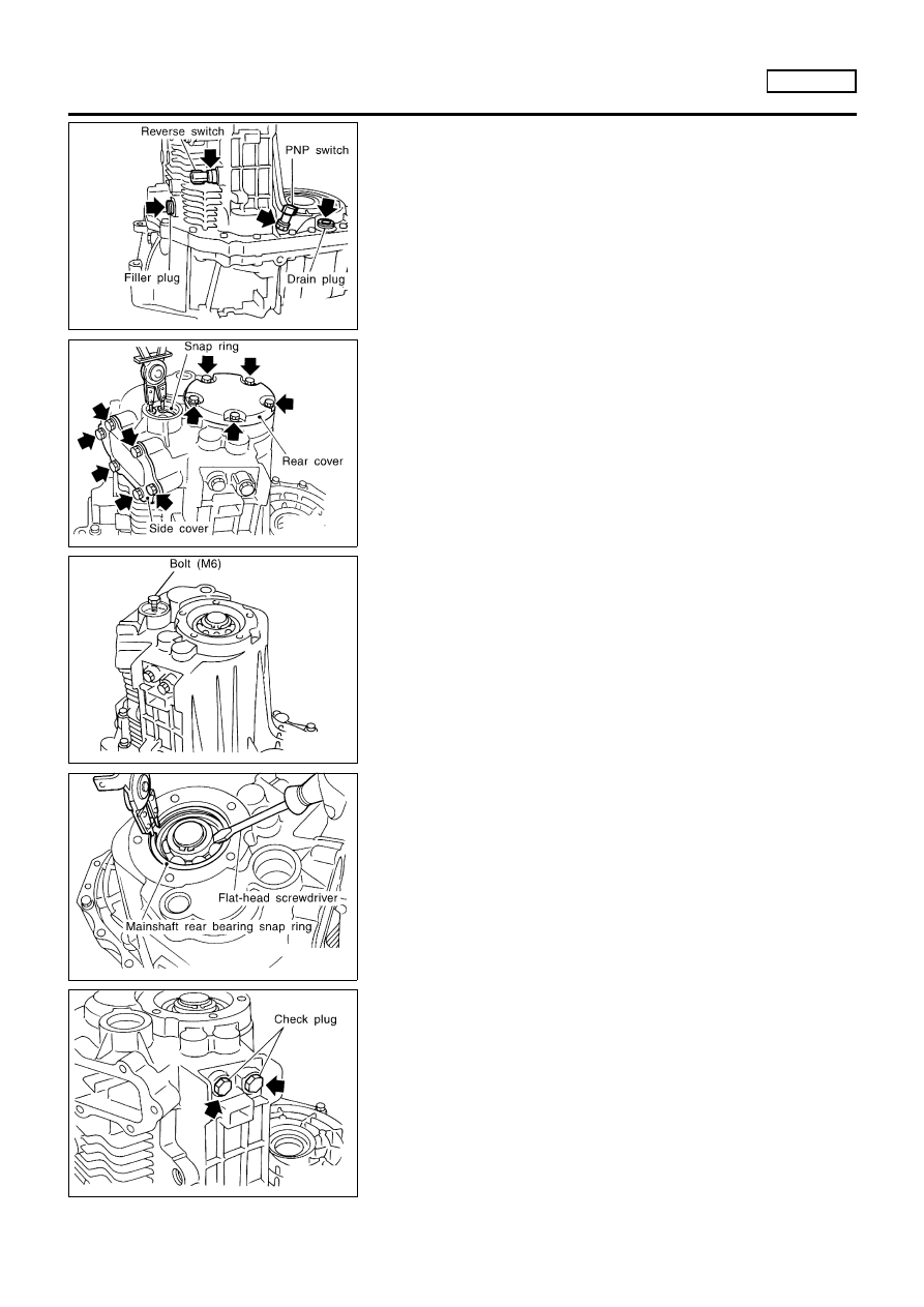
Remove reverse switch, PNP switch, drain plug, and filler plug
from transaxle case.

SMT644D

2.

Remove snap rings from reverse idler shaft.

3.

Remove side cover and rear cover from case.

4.

Remove O-ring and mainshaft bearing adjusting shim.

SMT645D

5.

Remove reverse idler gear shaft.

a.

Attach bolt (M6) to thread of reverse idler gear shaft end.

b.

Pull out the attached bolt, and remove reverse idler gear shaft
from case.

6.

Remove reverse idler gear, thrust washer (front, rear), and
bearing from case.

SMT646D

7.

Remove snap ring of mainshaft bearing from case.

SMT647D

8.

Remove check plugs, springs, and check balls from case.

DISASSEMBLY

RS5F70A

Transaxle Case

MT-28

SMT649D

9.

Remove mounting bolts.

10. Remove input shaft rear bearing adjusting shim from transaxle

case.

SMT650D

11. Remove oil gutter from case.

SMT651DB

12. Remove differential side bearing outer race and adjusting shim

from case.

SMT653DB

13. Remove differential oil seal from case.

SMT839DB

14. Remove welch plugs from case.

DISASSEMBLY

RS5F70A

Transaxle Case (Cont’d)

MT-29

SMT654D

Clutch Housing

NLMT0055S02

1.

Remove transaxle case from clutch housing.

2.

Remove magnet from housing.

3.

Remove check plugs, check springs, check pins, and check
balls from housing.

SMT656DC

4.

Remove 3rd & 4th bracket retaining pin.

SMT655D

5.

Remove 3rd & 4th shift fork stopper ring.

6.

Remove 3rd & 4th fork rod.

7.

Remove 3rd & 4th shift fork and bracket.

SMT658D

8.

Remove interlock plunger and check ball.

9.

Remove 5th & reverse bracket stopper ring.

SMT657DC

10. Remove retaining pin from 5th & reverse shift fork and reverse

switch bracket.

11. Remove 5th & reverse fork rod.
12. Remove interlock pin from 5th & reverse fork rod.
13. Remove reverse switch bracket and 5th & reverse bracket.

DISASSEMBLY

RS5F70A

Clutch Housing

MT-30

SMT659DC

14. Remove check ball from housing.
15. Remove retaining pin for 1st & 2nd shift fork and bracket.
16. Remove 1st & 2nd fork rod.
17. Remove 5th & reverse and 1st & 2nd shift forks, and 1st & 2nd

bracket.

SMT660D

18. Remove both input shaft and mainshaft assemblies from hous-

ing.

SMT661D

19. Remove final drive assembly from housing.
20. Remove oil pocket from housing.

SMT662D

21. Remove mainshaft bearing retainer from housing.
22. Cut off oil channel using a cutter as shown in the figure.

SMT663DB

23. Remove mainshaft front bearing from housing.

DISASSEMBLY

RS5F70A

Clutch Housing (Cont’d)

MT-31

SMT664D

24. Using a magnet or other suitable tool, remove retaining pin

from selector shaft.

SMT665DB

25. Remove selector shaft and plug, then remove selector.

SMT666DA

26. Remove reamer bolt, then remove select check leaf spring,

return spring, steel ball, reverse gate, selector arm, bearing,
and bushing.

CAUTION:

Be careful not to lose the steel ball.

SMT667DB

27. Remove retaining pin and plug from striking lever.
28. Remove striking rod, then striking lever from housing.

SMT668D

29. Using a flat-head screwdriver or other suitable tool, remove

dust seal, input shaft oil seal, and striking rod oil seal from
housing.

CAUTION:

When removing dust and oil seals, be careful not to damage
mounting surfaces of dust seal and oil seal.

DISASSEMBLY

RS5F70A

Clutch Housing (Cont’d)

MT-32

SMT669DB

30. Remove differential oil seal from housing.

SMT670DB

31. Remove differential side outer race from housing.

DISASSEMBLY

RS5F70A

Clutch Housing (Cont’d)

MT-33

SMT759D

Input Shaft and Gears

DISASSEMBLY

NLMT0056

1.

Before disassembly, measure the end plays of 3rd and 4th
input gears.

Gear end play:

Refer to SDS, MT-89.

+

If end play is not within specification, disassemble and check
the parts.

SMT671D

2.

Remove oil channel from input shaft rear bearing.

SMT672DB

3.

Press out input shaft rear bearing.

SMT673D

4.

Remove C-ring holder.

5.

Remove 5th gear rear C-ring.

SMT674DB

6.

Remove 5th input gear from input shaft.

7.

Remove 5th gear front C-ring.

REPAIR FOR COMPONENT PARTS

RS5F70A

Input Shaft and Gears

MT-34

SMT675DB

8.

Remove 4th input gear, baulk ring, 4th gear needle bearing,
and 4th gear C-ring from input shaft.

9.

Press out both 3rd & 4th synchronizer hub assembly and 3rd
input gear from input shaft.

10. Remove 3rd gear needle bearing.

SMT676DB

11. Press out input shaft front bearing from input shaft.

SMT693D

INSPECTION

NLMT0057

Input Shaft and Gears

NLMT0057S01

+

Check shaft for cracks, wear or bending.

+

Check gears for excessive wear, chips or cracks.

SMT637A

Synchronizers

NLMT0057S02

+

Check spline area of coupling sleeves, hubs and gears for
wear or cracks.

+

Check baulk rings for cracks or deformation.

+

Check insert springs for wear or deformation.

SMT867D

+

If any crack, damage, or excessive wear is found on cam face
of baulk ring or working face of insert, replace it.

REPAIR FOR COMPONENT PARTS

RS5F70A

Input Shaft and Gears (Cont’d)

MT-35

SMT841D

+

Measure the movement (play, dimension “L”) of 3rd & 4th cou-
pling sleeve with their end fixed and the other end lifted as
shown in the figure. If the movement exceeds specification,
replace the sleeve.

Coupling sleeve length “L”:

Refer to SDS, MT-89.

SMT140

+

Measure clearance between baulk ring and gear.

Clearance between baulk ring and gear:

Refer to SDS, MT-89.

SMT148A

Bearing

NLMT0057S03

+

Make sure bearings roll freely and are free from noise, cracks,
pitting or wear.

SMT696DB

ASSEMBLY

NLMT0058

1.

Press on input shaft front bearing.

2.

Install 3rd gear needle, 3rd input gear and 3rd gear baulk ring
bearing to input shaft.

SMT694D

3.

Install spread spring, shifting insert, and 3rd & 4th synchronizer
hub onto 3rd & 4th coupling sleeve.

+

Pay attention to the shape of spread spring and shifting insert
for correct assembly.
Do not install spread spring hook onto the same shifting insert.

CAUTION:

Do not reuse 3rd & 4th synchronizer hub.

REPAIR FOR COMPONENT PARTS

RS5F70A

Input Shaft and Gears (Cont’d)

MT-36

SMT695D

+

Install synchronizer hub with its three grooves facing the front
side (3rd input gear side).

SMT699D

+

Install 3rd & 4th coupling sleeve with its chamfered surface
facing the 4th input gear side.

SMT698DB

4.

Position bearing replacer to the front side of input shaft front
bearing.

+

Align grooves of shifting insert and 3rd gear baulk ring. Then,
press it onto 3rd & 4th synchronizer hub assembly using a drift.

5.

Install 4th gear C-ring onto input shaft.

SMT700DA

6.

Measure the end play of 3rd & 4th synchronizer hub, and
check if it is within allowable specification below.

End play:

0 - 0.06 mm (0 - 0.0024 in)

7.

If not within specification, adjust the end play by changing
thickness of 4th input gear C-ring.

4th input gear C-ring:

Refer to SDS, MT-90.

SMT701DB

8.

Install 4th gear needle bearing, 4th gear baulk ring, and 5th
gear front C-ring.

9.

Install 4th input gear.

REPAIR FOR COMPONENT PARTS

RS5F70A

Input Shaft and Gears (Cont’d)

MT-37

SMT703D

10. Position 5th input gear as shown in the figure, and install it on

input shaft.

SMT702DB

11. Install 5th input gear.

CAUTION:

Do not reuse 5th input gear.
12. Install 5th gear rear C-ring onto input shaft.

SMT704DA

13. Measure the end play of 5th input gear, and check if it is within

the allowable specification below.

End play:

0 - 0.06 mm (0 - 0.0024 in)

14. If not within specification, adjust the end play by changing

thickness of the 5th input gear rear C-ring.

5th input gear rear C-ring:

Refer to SDS, MT-90.

SMT705DB

15. Install C-ring holder onto 5th gear rear C-ring.

CAUTION:

Do not reuse C-ring holder.
16. Install input shaft rear bearing.

CAUTION:

Install input shaft rear bearing with its brown surface facing
the input gear side.

SMT671D

17. Install oil channel onto input shaft.
18. Measure gear end play as a final check. Refer to, MT-34.

REPAIR FOR COMPONENT PARTS

RS5F70A

Input Shaft and Gears (Cont’d)

MT-38

SMT760D

Mainshaft and Gears

DISASSEMBLY

NLMT0059

1.

Before disassembly, measure gear end play.

Gear end play:

Refer to SDS, MT-89.

+

If end play is not within the specificed limit, disassemble and
check the parts.

SMT677D

2.

Remove snap ring.

SMT678D

3.

Remove C-ring holder and mainshaft C-ring.

SMT679DB

4.

Press out mainshaft rear bearing from mainshaft.

SMT680D

5.

Remove mainshaft thrust washer.

6.

Remove snap ring from mainshaft. Then, remove reverse main
gear assembly, reverse gear needle bearing, and reverse gear
baulk ring.

REPAIR FOR COMPONENT PARTS

RS5F70A

Mainshaft and Gears

MT-39

SMT681DB

7.

Place bearing replacer between 5th & reverse synchronizer
hub and 5th main gear, and press out both reverse gear bush-
ing and 5th & reverse synchronizer assembly.

8.

Remove 5th main gear, 5th gear baulk ring, and 5th gear
needle bearing.

SMT682DB

9.

Place bearing replacer between 3rd and 4th main gears, and
press out both 5th gear bushing and 4th main gear.

SMT683D

10. Remove mainshaft adjusting shim and spacer.
11. Place bearing replacer between 2nd main gear and 1st & 2nd

synchronizer hub, and press out both 3rd and 2nd main gears.

SMT684DB

12. Remove 2nd double cone assembly, 2nd gear bushing, and

coupling sleeve assembly.

13. Place bearing replacer on 1st gear front side, and press out all

of 2nd gear bushing, 1st & 2nd synchronizer hub, 1st main
gear, and 1st double cone.

14. Remove 1st gear needle bearing.

SMT693D

INSPECTION

NLMT0060

Mainshaft and Gears

NLMT0060S01

+

Check shaft for cracks, wear or bending.

+

Check gears for excessive wear, chips or cracks.

REPAIR FOR COMPONENT PARTS

RS5F70A

Mainshaft and Gears (Cont’d)

MT-40

SMT637A

Synchronizers

NLMT0060S02

+

Check spline area of coupling sleeves, hubs and gears for
wear or cracks.

+

Check baulk rings for cracks or deformation.

+

Check insert springs for wear or deformation.

SMT867D

+

If any crack, damage, or excessive wear is found on cam face
of baulk ring or working face of insert, replace it.

SMT868D

+

Measure the movement (play, dimension “L”) of 1st & 2nd
coupling sleeve and 5th & reverse coupling sleeve with their
end fixed and the other end lifted as shown in the figure. If the
movement exceeds specification, replace the sleeve.

Coupling sleeve length “L”:

Refer to SDS, MT-89.

SMT140

+

Measure clearance between baulk ring and gear.

Clearance between baulk ring and gear:

Refer to SDS, MT-89.

SMT714CD

REPAIR FOR COMPONENT PARTS

RS5F70A

Mainshaft and Gears (Cont’d)

MT-41

+

Measure wear of 1st and 2nd baulk ring.

a)

Place baulk rings in position on synchronizer cone.

b)

While holding baulk ring against synchronizer cone as far as it
will go, measure dimensions “A” and “B”.

Standard:

A 0.6 - 0.8 mm (0.024 - 0.031 in)
B 0.6 - 1.1 mm (0.024 - 0.043 in)

Wear limit:

0.2 mm (0.008 in)

+

If dimension “A” or “B” is smaller than the wear limit,
replace outer baulk ring, inner baulk ring and synchro-
nizer cone as a set.

SMT148A

Bearing

NLMT0060S03

+

Make sure bearings roll freely and are free from noise, cracks,
pitting or wear.

SMT706D

ASSEMBLY

NLMT0061

1.

Install 1st gear needle bearing and 1st main gear onto main-
shaft.

2.

Install 1st double cone assembly onto mainshaft.

REPAIR FOR COMPONENT PARTS

RS5F70A

Mainshaft and Gears (Cont’d)

MT-42

SMT695D

3.

Install 1st & 2nd synchronizer hub with its three grooves fac-
ing the front side (1st main gear side) onto mainshaft.

CAUTION:

Do not reuse 1st & 2nd synchronizer hub.

SMT707DB

4.

Install 1st & 2nd synchronizer hub.

SMT994BB

5.

Install insert spring onto 1st & 2nd coupling sleeve.

SMT708D

6.

Install 1st & 2nd coupling sleeve with its chamfered surface
facing the 1st main gear side onto 1st & 2nd synchronizer hub.

SMT709DB

7.

Install 2nd gear bushing with its flange surface facing 1st & 2nd
synchronizer hub side.

REPAIR FOR COMPONENT PARTS

RS5F70A

Mainshaft and Gears (Cont’d)

MT-43


Content      ..     175      176      177      178     ..