Nissan Almera Tino V10 (2001 year). Manual - part 176
NLMT0034
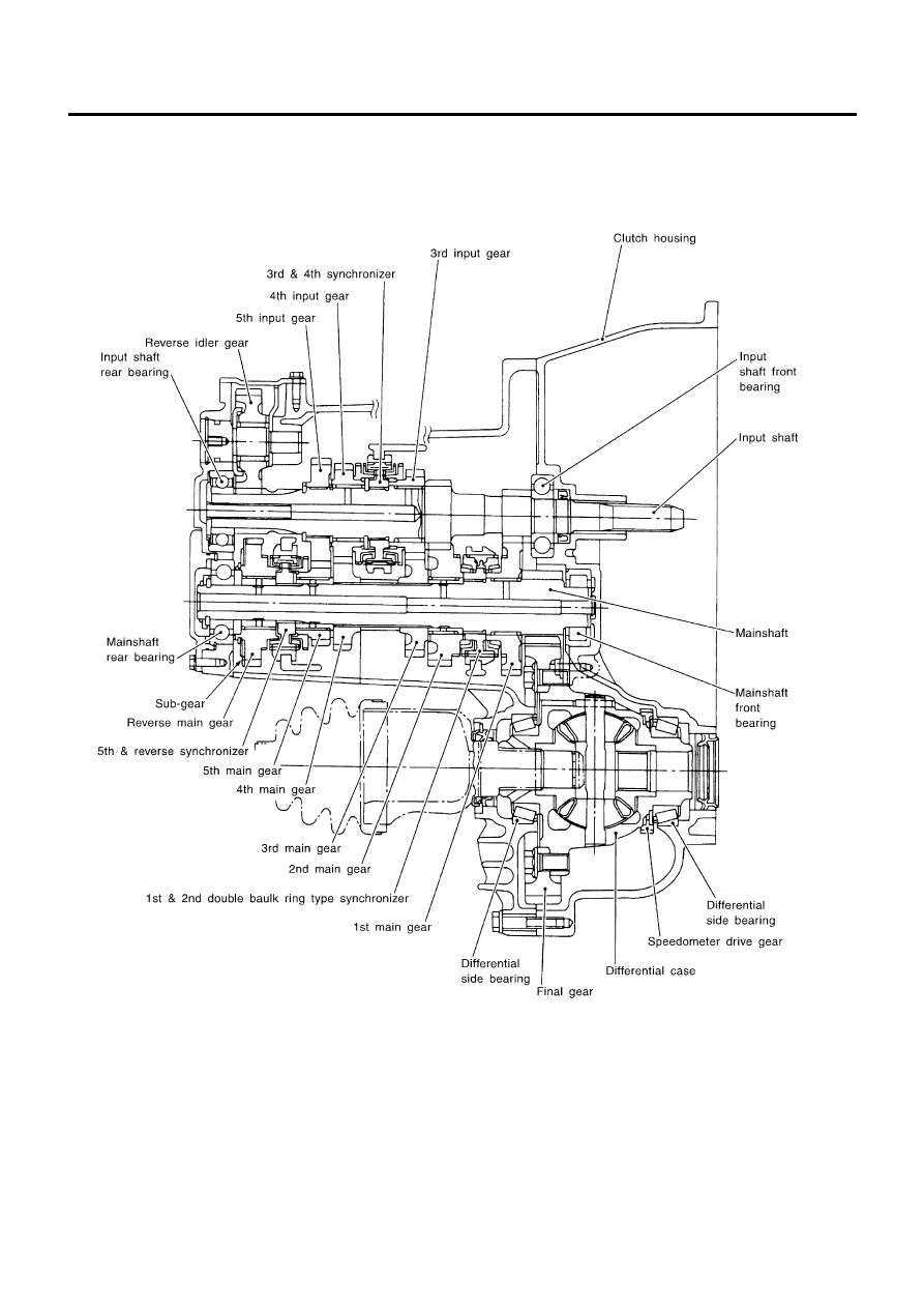
Cross-sectional View — RS5F70A
NLMT0034S03
SMT924D
DESCRIPTION
Cross-sectional View — RS5F70A
MT-12
|
|
|
NLMT0034 Cross-sectional View — RS5F70A NLMT0034S03 SMT924D DESCRIPTION Cross-sectional View — RS5F70A MT-12 |