Nissan Almera Tino V10 (2001 year). Manual - part 173
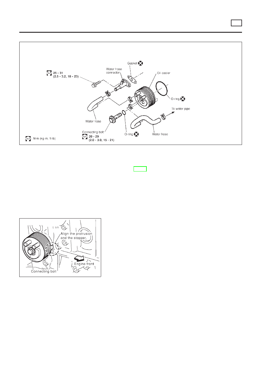
Oil Cooler
NLLC0077
NLC096
REMOVAL AND INSTALLATION
NLLC0077S01
1.
Draining the coolant
Refer to LC-59, “Changing Engine Coolant”.
2.
Remove the exhaust front tube.
SLC359B
3.
Reinstall all removed parts in the reverse order of removal.
+
Confirm that no foreign objects are adhering to the installation
planes of the oil cooler or block.
+
Tighten the connecting bolt after aligning the stopper on the
cylinder block side with protrusion of the oil cooler.
ENGINE LUBRICATION SYSTEM
YD
Oil Cooler
LC-50