Nissan Almera Tino V10 (2001 year). Manual - part 129
Trouble Diagnoses
NLEL0482
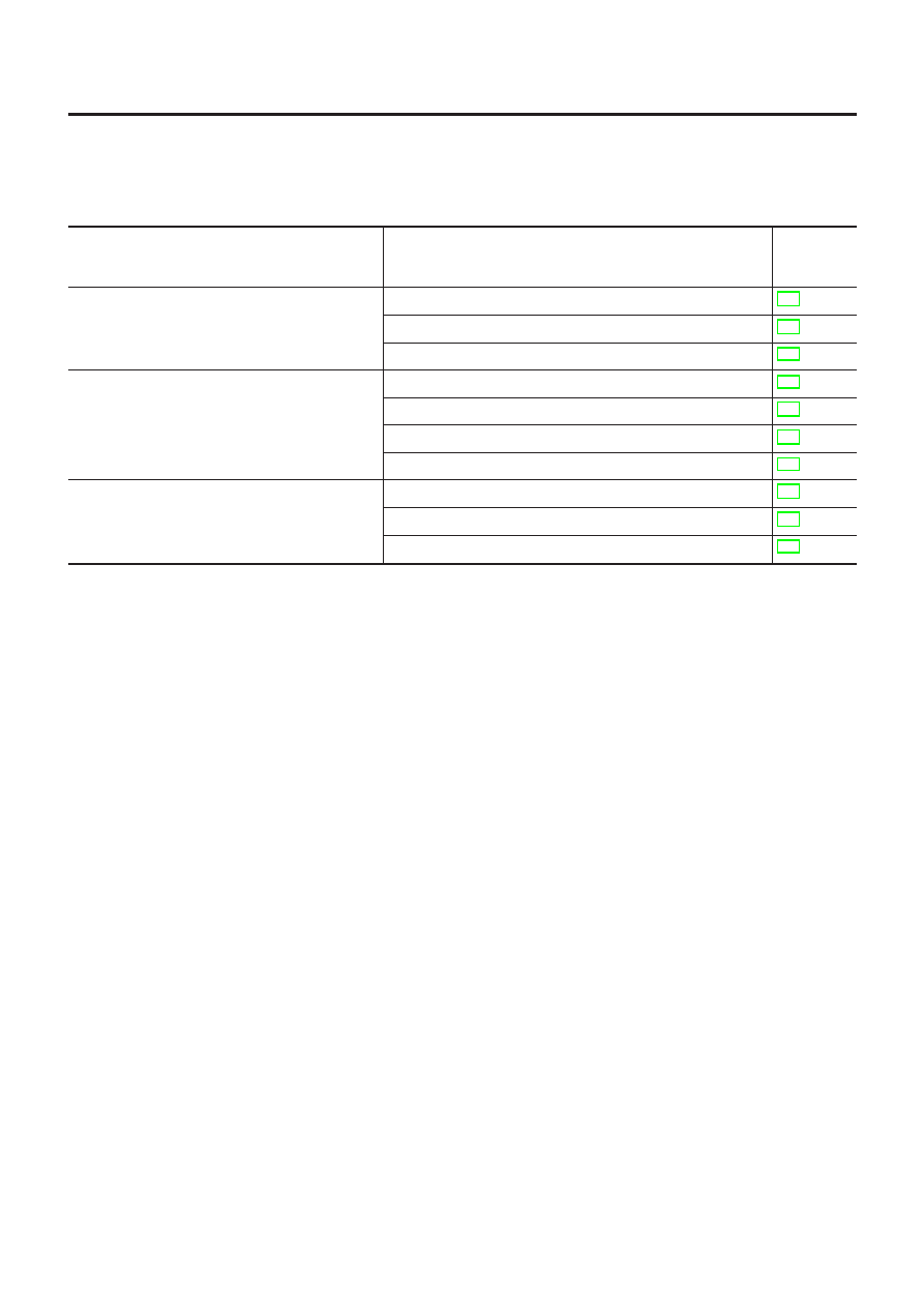
SYMPTOM CHART
NLEL0482S01
NOTE:
Always check remote controller battery before replacing remote
controller.
Symptom
Diagnoses/service procedure
Reference
page
(EL-
)
No doors can be locked or unlocked by remote
control operation.
(Make sure that power door lock operates prop-
erly. If NG, check power door lock.)
1. Remote controller battery check
2. Power supply and ground circuit for time control unit check
3. Replace remote controller. Refer to ID Code Entry Procedure. 324
The new ID of remote controller cannot be
entered.
1. Remote controller battery check
2. Power supply and ground circuit for time control unit check
3. Ignition “ON” power supply circuit for time control unit
4. Replace remote controller. Refer to ID Code Entry Procedure. 324
Hazard reminder does not activate properly when
pressing lock or unlock button of remote controller.
1. Remote controller battery
2. Hazard reminder check
3. Replace remote controller. Refer to ID Code Entry Procedure. 324
MULTI-REMOTE CONTROL SYSTEM
Trouble Diagnoses
EL-319