Nissan Almera Tino V10 (2001 year). Manual - part 122


  Index      Manuals     Nissan Almera Tino V10 (2001 year) - Service and Repair Manual


Search            copyright infringement  


Content      ..     120      121      122      123     ..


Nissan Almera Tino V10 (2001 year). Manual - part 122


Filament Repair

NLEL0078

REPAIR EQUIPMENT

NLEL0078S01

1)

Conductive silver composition (Dupont No. 4817 or equivalent)

2)

Ruler 30 cm (11.8 in) long

3)

Drawing pen

4)

Heat gun

5)

Alcohol

6)

Cloth

BE540

REPAIRING PROCEDURE

NLEL0078S02

1.

Wipe broken heat wire and its surrounding area clean with a
cloth dampened in alcohol.

2.

Apply a small amount of conductive silver composition to tip of
drawing pen.

Shake silver composition container before use.
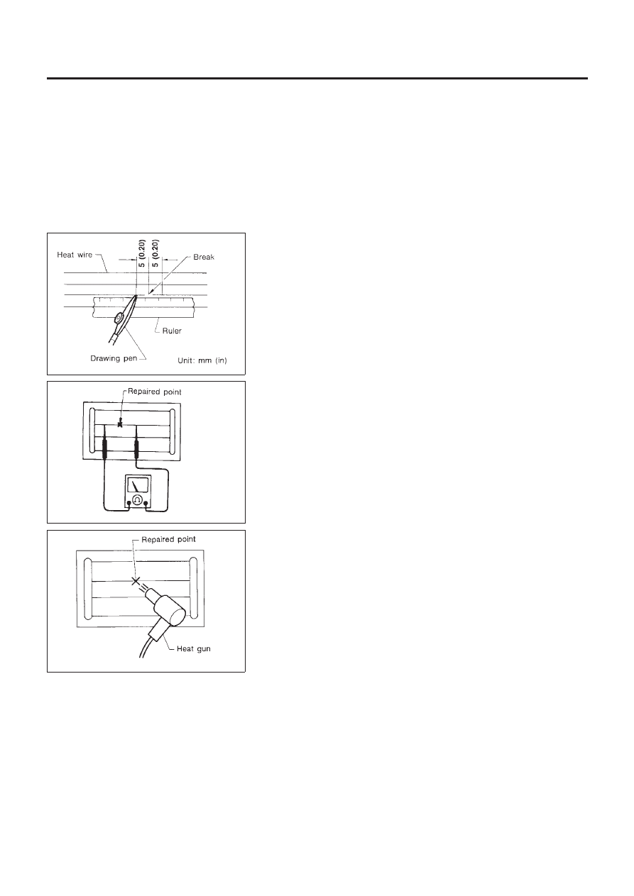
3.

Place ruler on glass along broken line. Deposit conductive sil-
ver composition on break with drawing pen. Slightly overlap
existing heat wire on both sides [preferably 5 mm (0.20 in)] of
the break.

SEL012D

4.

After repair has been completed, check repaired wire for con-
tinuity. This check should be conducted 10 minutes after silver
composition is deposited.

Do not touch repaired area while test is being conducted.

SEL013D

5.

Apply a constant stream of hot air directly to the repaired area
for approximately 20 minutes with a heat gun. A minimum dis-
tance of 3 cm (1.2 in) should be kept between repaired area
and hot air outlet. If a heat gun is not available, let the repaired
area dry for 24 hours.

REAR WINDOW DEFOGGER

Filament Repair

EL-207

System Description

=NLEL0497

Refer to Owner’s Manual for audio system operating instructions.
Power is supplied at all times

+

through 15A fuse

+

to audio unit terminal 9

+

to CD auto changer terminal 32.

With the ignition switch in the ACC or ON position, power is supplied

+

through 10A fuse [No. 1, located in the fuse block (J/B)]

+

to audio unit terminal 3,

+

to CD auto changer terminal 36 and

Ground is supplied through the case of the audio unit.
Audio signals are supplied

+

through audio unit terminals 7, 10, 11, 12, 13, 14, 15, 16

+

to terminals 1 and 2 of front door speaker LH and RH,

+

to terminals 1 and 2 of rear door speaker LH and RH and

+

to terminals 1 and 2 of pillar tweeter LH and RH (with 6 speakers)

When the navigation system is triggered,
power is supplied

+

through navi control unit terminal 46

+

to speaker relay terminal 2

Ground is supplied

+

through navi control unit terminal 44

+

to speaker relay terminal 1

With power and ground supplied, the relay is energized, and then audio signal is interrupted to front door
speaker RH (LHD models) or LH (RHD models), and pillar tweeter RH (LHD models) or LH (RHD models)
For detailed, refer to “NAVIGATION SYSTEM”.

NATS AUDIO LINK

NLEL0497S01

Description

NLEL0497S0101

The link with the NATS IMMU implies that the audio unit can basically only be operated if connected to the
matching NATS IMMU to which the audio unit was initially fitted on the production line.
Since radio operation is impossible after the link with the NATS is disrupted theft of the audio unit is basically
useless since special equipment is required to reset the audio unit.
Initialization process for audio units that are linked to the NATS IMMU
New audio units will be delivered to the factories in the “NEW” state, i.e. ready to be linked with the vehicle’s
NATS. When the audio unit in “NEW” state is first switched on at the factory, it will start up communication
with the vehicle’s immobiliser control unit (IMMU) and send a code (the “audio unit Code”) to the IMMU. The
IMMU will then store this code, which is unique to each audio unit, in its (permanent) memory.
Upon receipt of the code by the IMMU, the NATS will confirm correct receipt of the audio unit code to the audio
unit. Hereafter, the audio unit will operate as normal.
During the initialisation process, “NEW” is displayed on the audio unit display. Normally though, communica-
tion between audio unit and IMMU takes such a short time (300 ms) that the audio unit seems to switch on
directly without showing “NEW” on its display.
Normal operation
Each time the audio unit is switched on afterwards, the audio unit code will be verified between the audio unit
and the NATS before the audio unit becomes operational. During the code verification process, “WAIT” is
shown on the audio unit display. Again, the communication takes such a short time (300 ms) that the audio
unit seems to switch on directly without showing “WAIT” on its display.
When the radio is locked
In case of a audio unit being linked with the vehicle’s NATS (immobilizer system), disconnection of the link
between the audio unit and the IMMU will cause the audio unit to switch into the lock (“SECURE”) mode in
which the audio unit is fully inoperative. Hence, repair of the audio unit is basically impossible, unless the audio
unit is reset to the “NEW” state for which special decoding equipment is required.
Clarion has provided their authorized service representatives with so called “decoder boxes” which can bring
the audio unit back to the “NEW” state, enabling the audio unit to be switched on after which repair can be

AUDIO

System Description

EL-208

carried out. Subsequently, when the repaired audio unit is delivered to the final user again, it will be in the
“NEW” state as to enable re-linking the audio unit to the vehicle’s immobiliser system. As a result of the above,
repair of the audio unit can only be done by an authorized Clarion representative.
Service instruction

Item

Radio linked with IMMU and/or SECU

Battery disconnection

No additional action required

Radio needs repair

Repair needs to be done by authorised representative of radio manufacturer since radio
cannot be operated unless it is reset to NEW state, using special decoding equipment

Replacement of radio by new part

Radio is delivered in NEW state. If possible, the radio will automatically link up with the
immobiliser system. If this appears not possible, CATS code needs to be manually input

Transferring radio to another vehicle /
replacement of radio by an “old” part

Radio needs to be reset to NEW state by authorised representative of radio manufacturer

Replacement of IMMU by new part

Radio will request for CATS code input prior to establishing the link with the IMMU

Replacement of IMMU by old part

If a radio code has already been stored in memory of the IMMU, the radio cannot be
linked to it. After switching on the radio, it will display “SECURE” after 1 minute. Operation
can only be established after resetting the ratio by an authorised representative of radio
manufacturer

No communication from IMMU to
radio

Radio will display “SECURE” after 180 attempts to communicate with IMMU. Further use
of radio impossible until communication is established again, or after radio is reset by
authorised representative of (radio) manufacturer

CATS code input procedure
1. Radio displays “CODE IN” after the power is switched ON.
2. Enter CATS code (4–digits) by pressing the preset buttons (using 1 to 4).

Press the preset buttons for the necessary amount of times for the number of each digits.
e.g. CATS code is “5432”
Press No. 1 preset button for 5 times
Press No. 2 preset button for 4 times
Press No. 3 preset button for 3 times
Press No. 4 preset button for 2 times

3. Press the

button.

4. If the code is OK, the radio will power ON.

If the code is NG, the radio will be locked up as below. After the lock up, the radio will display “CODE IN”
again.
1st to 3rd attempt: The radio will be locked for 10 seconds after each attempt
4th to 20th attempt: The radio will be locked for 60 minutes after each attempt
Over 20th attempt: The radio will be locked completely

SPEED DEPENDENT VOLUME CONTROL

NLEL0497S02

Description

NLEL0497S0201

If activated, the radio output volume will be automatically adjusted to compensate for increasing driving noises
at higher driving speeds.
The radio receives a speed signal from the vehicle speed sensor (VSS) and selects the output volume.

PERSONAL AUDIO SETTINGS

NLEL0497S03

Description

NLEL0497S0301

The radio is designed to store several settings (volume, bass, treble, preset stations and level of speed
dependent volume control) with every NATS ignition key used. Up to a maximum of 4 NATS keys can be reg-
istered. During the communication as mentioned under “NATS audio link”, the radio will recognize the used
ignition key and select the accompanying settings.

AUDIO

System Description (Cont’d)

EL-209

Schematic

NLEL0466

WHERE

FITTED-1

NLEL0466S01

YEL913B

AUDIO

Schematic

EL-210

WHERE

FITTED-2

NLEL0466S02

YEL434C

AUDIO

Schematic

(Cont’d)

EL-21

1

Wiring Diagram — AUDIO —

NLEL0467

MODELS WITH FUSE AND FUSIBLE LINK BOX E43

NLEL0467S03

YEL914B

AUDIO

Wiring Diagram — AUDIO —

EL-212

YEL915B

AUDIO

Wiring Diagram — AUDIO — (Cont’d)

EL-213

YEL916B

AUDIO

Wiring Diagram — AUDIO — (Cont’d)

EL-214

YEL917B

AUDIO

Wiring Diagram — AUDIO — (Cont’d)

EL-215

YEL918B

AUDIO

Wiring Diagram — AUDIO — (Cont’d)

EL-216

YEL919B

AUDIO

Wiring Diagram — AUDIO — (Cont’d)

EL-217

YEL920B

AUDIO

Wiring Diagram — AUDIO — (Cont’d)

EL-218

YEL921B

AUDIO

Wiring Diagram — AUDIO — (Cont’d)

EL-219

MODELS WITH FUSE AND FUSIBLE LINK BOX E90

NLEL0467S04

LHD and RHD models

NLEL0467S0401

YEL435C

AUDIO

Wiring Diagram — AUDIO — (Cont’d)

EL-220

YEL436C

AUDIO

Wiring Diagram — AUDIO — (Cont’d)

EL-221

YEL437C

AUDIO

Wiring Diagram — AUDIO — (Cont’d)

EL-222


Content      ..     120      121      122      123     ..