Nissan Almera Tino V10 (2001 year). Manual - part 48


  Index      Manuals     Nissan Almera Tino V10 (2001 year) - Service and Repair Manual


Search            copyright infringement  


Content      ..     46      47      48      49     ..


Nissan Almera Tino V10 (2001 year). Manual - part 48


2

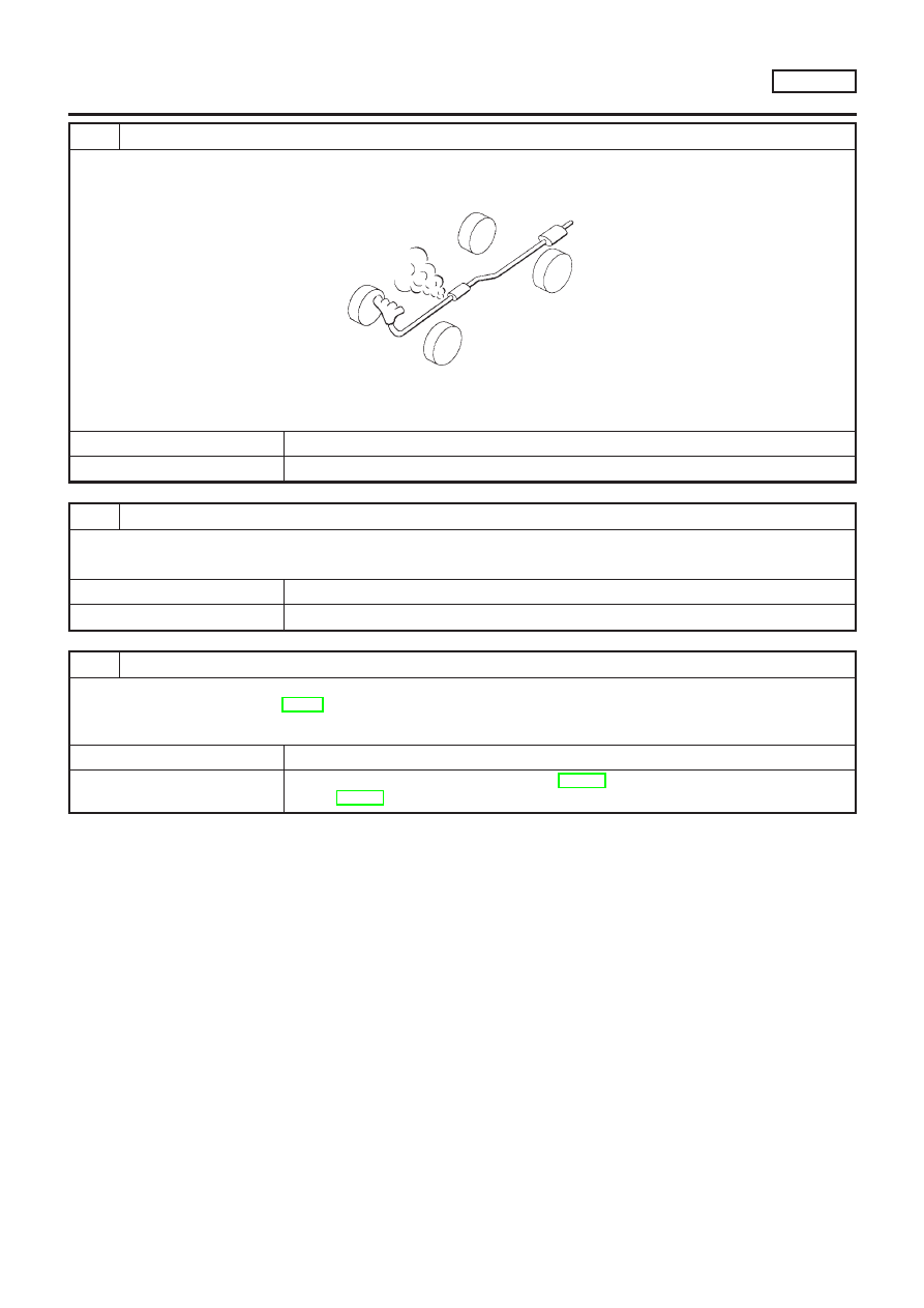
CHECK EXHAUST AIR LEAK

1. Start engine and run it at idle.
2. Listen for an exhaust air leak before the three way catalyst.

SEF099P

OK or NG

OK

©

GO TO 3.

NG

©

Repair or replace.

3

CHECK INTAKE AIR LEAK

Listen for an intake air leak after the mass air flow sensor.

OK or NG

OK

©

GO TO 4.

NG

©

Repair or replace.

4

CHECK IGNITION TIMING

Check for ignition timing.
Refer to “BASIC INSPECTION”, EC-99.

OK or NG

OK

©

GO TO 5.

NG

©

Check camshaft position sensor (PHASE) (EC-302) and crankshaft position sensor
(POS) (EC-295).

DTC P0420 THREE WAY CATALYST FUNCTION

QG18DE

Diagnostic Procedure (Cont’d)

EC-329

5

CHECK INJECTORS

1. Refer to Wiring Diagram for Injectors, EC-495.
2. Stop engine and then turn ignition switch “ON”.
3. Check voltage between ECM terminals 101, 103, 105 and 107 and ground with CONSULT-II or tester.

SEF075X

Battery voltage should exist.

OK or NG

OK

©

GO TO 6.

NG

©

Perform “Diagnostic Procedure” INJECTOR, EC-497.

6

CHECK IGNITION SPARK

1. Disconnect ignition coil assembly from rocker cover.
2. Connect a known good spark plug to the ignition coil assembly.
3. Place end of spark plug against a suitable ground and crank engine.
4. Check for spark.

SEF575Q

OK or NG

OK

©

GO TO 7.

NG

©

Check ignition coil, power transistor and their circuits. Refer to EC-500.

7

CHECK INJECTOR

1. Turn ignition switch “OFF”.
2. Remove injector assembly. Refer to EC-44.

Keep fuel hose and all injectors connected to injector gallery.

3. Disconnect camshaft position sensor harness connector.
4. Turn ignition switch “ON”.

Make sure fuel does not drip from injector.

OK or NG

OK (Does not drip)

©

GO TO 8.

NG (Drips)

©

Replace the injector(s) from which fuel is dripping.

DTC P0420 THREE WAY CATALYST FUNCTION

QG18DE

Diagnostic Procedure (Cont’d)

EC-330

8

CHECK INTERMITTENT INCIDENT

Perform “TROUBLE DIAGNOSIS FOR INTERMITTENT INCIDENT”, EC-145.

Trouble is fixed

©

INSPECTION END

Trouble is not fixed

©

Replace three way catalyst.

DTC P0420 THREE WAY CATALYST FUNCTION

QG18DE

Diagnostic Procedure (Cont’d)

EC-331

Description

NLEC0248

SYSTEM DESCRIPTION

NLEC0248S01

Sensor

Input Signal to ECM

ECM func-

tion

Actuator

Crankshaft position sensor (POS)

Engine speed

EVAP can-
ister purge
control

EVAP canister purge volume
control solenoid valve

Camshaft position sensor (PHASE)

Engine speed and cylinder number

Mass air flow sensor

Amount of intake air

Engine coolant temperature sensor

Engine coolant temperature

Battery

Battery voltage

Ignition switch

Start signal

Closed throttle position switch

Closed throttle position

Throttle position sensor

Throttle position

Heated oxygen sensor 1 (front)

Density of oxygen in exhaust gas
(Mixture ratio feedback signal)

Vehicle speed sensor

Vehicle speed

This system controls flow rate of fuel vapor from the EVAP canis-
ter. The opening of the vapor by-pass passage in the EVAP canis-
ter purge volume control solenoid valve changes to control the flow
rate. The EVAP canister purge volume control solenoid valve
repeats ON/OFF operation according to the signal sent from the
ECM. The opening of the valve varies for optimum engine control.
The optimum value stored in the ECM is determined by consider-
ing various engine conditions. When the engine is operating, the
flow rate of fuel vapor from the EVAP canister is regulated as the
air flow changes.

SEF337U

COMPONENT DESCRIPTION

NLEC0248S02

The EVAP canister purge volume control solenoid valve uses a
ON/OFF duty to control the flow rate of fuel vapor from the EVAP
canister. The EVAP canister purge volume control solenoid valve
is moved by ON/OFF pulses from the ECM. The longer the ON
pulse, the greater the amount of fuel vapor that will flow through the
valve.

CONSULT-II Reference Value in Data Monitor
Mode

NLEC0249

MONITOR ITEM

CONDITION

SPECIFICATION

PURG VOL C/V

+

Engine: After warming up

+

No-load

Idle

0%

Revving engine

DTC P0443 EVAP CANISTER PURGE VOLUME CONTROL SOLENOID VALVE

(CIRCUIT)

QG18DE

Description

EC-332

ECM Terminals and Reference Value

=NLEC0250

Specification data are reference values and are measured between each terminal and ground.

CAUTION:

Do not use ECM ground terminals when measuring input/output voltage. Doing so may result in dam-
age to the ECM’s transistor. Use a ground other than ECM terminals, such as the ground.

TER-

MINAL

NO.

WIRE

COLOR

ITEM

CONDITION

DATA (DC Voltage)

14

GY/L

EVAP canister purge vol-
ume control solenoid valve

[Engine is running]

+

Warm-up condition

+

Idle speed

BATTERY VOLTAGE
(11 - 14V)

[Engine is running]

+

Warm-up condition

+

2,000 rpm

5 - 12V

SEF975W

On Board Diagnosis Logic

NLEC0251

DTC No.

Malfunction is detected when ...

Check Items (Possible Cause)

P0443
0443

+

An improper voltage signal is sent to ECM through the
valve.

+

Harness or connectors
(The valve circuit is open or shorted.)

+

EVAP canister purge volume control solenoid
valve

DTC Confirmation Procedure

NLEC0252

NOTE:
If “DTC Confirmation Procedure” has been previously conducted,
always turn ignition switch “OFF” and wait at least 9 seconds
before conducting the next test.
TESTING CONDITION:
Before performing the following procedure, confirm battery
voltage is more than 11V.

SEF058Y

With CONSULT-II

1)

Turn ignition switch “ON”.

2)

Select “DATA MONITOR” mode with CONSULT-II.

3)

Start engine and let it idle for at least 5 seconds.

4)

If

1st

trip

DTC

is

detected,

go

to

“DIAGNOSTIC

PROCEDURE”, EC-336.

With GST

Follow the procedure “With CONSULT-II” above.

DTC P0443 EVAP CANISTER PURGE VOLUME CONTROL SOLENOID VALVE

(CIRCUIT)

QG18DE

ECM Terminals and Reference Value

EC-333

Wiring Diagram

NLEC0253

MODELS WITH ECM IN ENGINE COMPARTMENT

NLEC0253S01

YEC666

DTC P0443 EVAP CANISTER PURGE VOLUME CONTROL SOLENOID VALVE

(CIRCUIT)

QG18DE

Wiring Diagram

EC-334

MODELS WITH ECM IN CABIN

NLEC0253S02

YEC886

DTC P0443 EVAP CANISTER PURGE VOLUME CONTROL SOLENOID VALVE

(CIRCUIT)

QG18DE

Wiring Diagram (Cont’d)

EC-335

Diagnostic Procedure

NLEC0254

1

CHECK POWER SUPPLY

1. Turn ignition switch “OFF”.
2. Disconnect EVAP canister purge volume control solenoid valve harness connector.

SEF076X

3. Turn ignition switch “ON”.
4. Check voltage between terminals 1 and engine ground with CONSULT-II or tester.

SEF606Y

OK or NG

OK

©

GO TO 3.

NG

©

GO TO 2.

2

DETECT MALFUNCTIONING PART

Check the following.

+

Harness connectors E75, F35 (where fitted)

+

Harness connectors M72, F44 (where fitted)

+

10A fuse

+

Harness for open or short between EVAP canister purge volume control solenoid valve and fuse

©

Repair harness or connectors.

3

CHECK OUTPUT SIGNAL CIRCUIT

1. Turn ignition switch “OFF”.
2. Disconnect ECM harness connector.
3. Check harness continuity between ECM terminal 14 and terminal 2.

Refer to wiring diagram.

Continuity should exist.

4. Also check harness for short to ground and short to power.

OK or NG

OK

©

GO TO 4.

NG

©

Repair open circuit or short to ground or short to power in harness or connectors.

DTC P0443 EVAP CANISTER PURGE VOLUME CONTROL SOLENOID VALVE

(CIRCUIT)

QG18DE

Diagnostic Procedure

EC-336

4

CHECK EVAP CANISTER PURGE VOLUME CONTROL SOLENOID VALVE

Refer to “Component Inspection” EC-337.

OK or NG

OK

©

GO TO 5.

NG

©

Replace EVAP canister purge volume control solenoid valve.

5

CHECK INTERMITTENT INCIDENT

Perform “TROUBLE DIAGNOSIS FOR INTERMITTENT INCIDENT”, EC-145.

©

INSPECTION END

SEF677Y

SEF661U

Component Inspection

NLEC0255

EVAP CANISTER PURGE VOLUME CONTROL
SOLENOID VALVE

NLEC0255S01

With CONSULT-II

1)

Start engine.

2)

Perform “PURG VOL CONT/V” in “ACTIVE TEST” mode with
CONSULT-II. Check that engine speed varies according to the
valve opening.
If OK, inspection end. If NG, go to following step.

3)

Check air passage continuity.

Condition

PURG VOL CONT/V value

Air passage continuity

between A and B

100.0%

Yes

0.0%

No

If NG, replace the EVAP canister purge volume control sole-
noid valve.

Without CONSULT-II

Check air passage continuity.

Condition

Air passage continuity

between A and B

12V direct current supply between ter-
minals

Yes

No supply

No

If NG, replace the EVAP canister purge volume control solenoid
valve.

DTC P0443 EVAP CANISTER PURGE VOLUME CONTROL SOLENOID VALVE

(CIRCUIT)

QG18DE

Diagnostic Procedure (Cont’d)

EC-337

SEF080X

Component Description

NLEC0272

The vehicle speed sensor is installed in the transaxle. It contains a
pulse generator which provides a vehicle speed signal to the
speedometer. The speedometer then sends a signal to the ECM.

ECM Terminals and Reference Value

NLEC0273

Specification data are reference values and are measured between each terminal and ground.

CAUTION:

Do not use ECM ground terminals when measuring input/output voltage. Doing so may result in dam-
age to the ECM’s transistor. Use a ground other than ECM terminals, such as the ground.

TER-

MINAL

NO.

WIRE

COLOR

ITEM

CONDITION

DATA (DC Voltage)

86

PU/R

Vehicle speed sensor

[Engine is running]

+

Lift up the vehicle

+

In 2nd gear position

+

Vehicle speed is 40 km/h (25 MPH)

2.5 - 3V

SEF976W

On Board Diagnosis Logic

NLEC0274

DTC No.

Malfunction is detected when ...

Check Items (Possible Cause)

P0500
0500

+

The almost 0 km/h (0 MPH) signal from vehicle speed
sensor is sent to ECM even when vehicle is being
driven.

+

Harness or connector
(The vehicle speed sensor circuit is open or
shorted.)

+

Vehicle speed sensor

DTC Confirmation Procedure

NLEC0275

CAUTION:

Always drive vehicle at a safe speed.
NOTE:
If “DTC Confirmation Procedure” has been previously conducted,
always turn ignition switch “OFF” and wait at least 9 seconds
before conducting the next test.
TESTING CONDITION:
This procedure may be conducted with the drive wheels lifted
in the shop or by driving the vehicle. If a road test is expected
to be easier, it is unnecessary to lift the vehicle.

DTC P0500 VEHICLE SPEED SENSOR (VSS)

QG18DE

Component Description

EC-338

SEF196Y

With CONSULT-II

1)

Start engine

2)

Read “VHCL SPEED SE” in “DATA MONITOR” mode with
CONSULT-II. The vehicle speed on CONSULT-II should
exceed 10 km/h (6 MPH) when rotating wheels with suitable
gear position.

3)

If NG, go to “Diagnostic Procedure”, EC-342.
If OK, go to following step.

4)

Select “DATA MONITOR” mode with CONSULT-II.

5)

Warm engine up to normal operating temperature.

6)

Maintain the following conditions for at least 10 consecutive
seconds.

ENG SPEED

2,600 - 4,000 rpm

COOLAN TEMP/S

More than 70°C (158°F)

B/FUEL SCHDL

5.3 - 10.7 msec

Selector lever

Suitable position

PW/ST SIGNAL

OFF

7)

If 1st trip DTC is detected, go to “Diagnostic Procedure”,
EC-342.

With GST

Follow the procedure “With CONSULT-II” above.

SEF607Y

Without CONSULT-II

1)

Lift up drive wheels.

2)

Start engine.

3)

Read the voltage signal between ECM terminal 86 (Vehicle
speed sensor signal) and ground with oscilloscope.

4)

Verify that the oscilloscope screen shows the signal wave as
shown in the figure.

5)

If NG, go to “Diagnostic Procedure”, EC-342.

DTC P0500 VEHICLE SPEED SENSOR (VSS)

QG18DE

DTC Confirmation Procedure (Cont’d)

EC-339

Wiring Diagram

NLEC0277

MODELS WITH ECM IN ENGINE COMPARTMENT

NLEC0277S03

YEC667

DTC P0500 VEHICLE SPEED SENSOR (VSS)

QG18DE

Wiring Diagram

EC-340

MODELS WITH ECM IN CABIN

NLEC0277S04

YEC887

DTC P0500 VEHICLE SPEED SENSOR (VSS)

QG18DE

Wiring Diagram (Cont’d)

EC-341

Diagnostic Procedure

NLEC0278

1 CHECK INPUT SIGNAL CIRCUIT

1. Turn ignition switch “OFF”.
2. Disconnect ECM harness connector and combination meter harness connector.
3. Check harness continuity between ECM terminal 86 and meter terminal 39.

Refer to wiring diagram.

Continuity should exist.

4. Also check harness for short to ground and short to power.

OK or NG

OK 

© 

GO TO 3.

NG 

© 

GO TO 2.

2 DETECT MALFUNCTIONING PART

Check the following.

+

Harness connectors M50, F38

+

Harness for open or short between ECM and combination meter

© 

Repair open circuit or short to ground or short to power in harness or connectors.

3 CHECK SPEEDOMETER FUNCTION

Make sure that speedometer functions properly.

OK or NG

OK 

© 

GO TO 5.

NG 

© 

GO TO 4.

4 CHECK SPEEDOMETER CIRCUIT

Check the following.

+

Harness connectors M50, F38 (where fitted)

+

Harness connectors M49, F43 (where fitted)

+

Harness connectors M71, F45 (where fitted)

+

Harness connectors M72, F44 (where fitted)

+

Harness for open or short between combination meter and vehicle speed sensor

OK 

© 

Check combination meter and vehicle speed sensor. Refer to EL-130, “METERS AND
GAUGES”.

NG 

© 

Repair open circuit or short to ground or short to power in harness or connectors.

5 CHECK INTERMITTENT INCIDENT

Perform “TROUBLE DIAGNOSIS FOR INTERMITTENT INCIDENT”, EC-145.

© 

INSPECTION END

DTC P0500 VEHICLE SPEED SENSOR (VSS) 

QG18DE

Diagnostic Procedure

EC-342

Description

NLEC0279

SYSTEM DESCRIPTION

NLEC0279S01

Sensor

Input Signal to ECM

ECM func-

tion

Actuator

Crankshaft position sensor (POS)

Engine speed

Idle air con-
trol

IACV-AAC valve

Camshaft position sensor (PHASE)

Engine speed and cylinder number

Engine coolant temperature sensor

Engine coolant temperature

Ignition switch

Start signal

Throttle position sensor

Throttle position

PNP switch

Park/Neutral position

Air conditioner switch

Air conditioner operation

Power steering oil pressure switch

Power steering load signal

Battery

Battery voltage

Vehicle speed sensor

Vehicle speed

Cooling fan

Cooling fan operation

Electrical load

Electrical load signal

This system automatically controls engine idle speed to a specified
level. Idle speed is controlled through fine adjustment of the
amount of air which by-passes the throttle valve via IACV-AAC
valve. The IACV-AAC valve changes the opening of the air by-pass
passage to control the amount of auxiliary air. This valve is actu-
ated by a step motor built into the valve, which moves the valve in
the axial direction in steps corresponding to the ECM output sig-
nals. One step of IACV-AAC valve movement causes the respec-
tive opening of the air by-pass passage. (i.e. when the step
advances, the opening is enlarged.) The opening of the valve is
varied to allow for optimum control of the engine idling speed. The
crankshaft position sensor (POS) detects the actual engine speed
and sends a signal to the ECM. The ECM then controls the step
position of the IACV-AAC valve so that engine speed coincides with
the target value memorized in ECM. The target engine speed is the
lowest speed at which the engine can operate steadily. The opti-
mum value stored in the ECM is determined by taking into consid-
eration various engine conditions, such as during warm up,
deceleration, and engine load (air conditioner, power steering, cool-
ing fan operation and electrical load).

SEF937W

COMPONENT DESCRIPTION

NLEC0279S02

IACV-AAC Valve

NLEC0279S0202

The IACV-AAC valve is operated by a step motor for centralized
control of auxiliary air supply. This motor has four winding phases
and is actuated by the output signals of ECM which turns ON and
OFF two windings each in sequence. Each time the IACV-AAC
valve opens or closes to change the auxiliary air quantity, the ECM
sends a pulse signal to the step motor. When no change in the
auxiliary air quantity is needed, the ECM does not issue the pulse
signal. A certain voltage signal is issued so that the valve remains
at that particular opening.

DTC P0505 IDLE AIR CONTROL VALVE (IACV) — AUXILIARY AIR CONTROL

(AAC) VALVE

QG18DE

Description

EC-343

CONSULT-II Reference Value in Data Monitor
Mode

NLEC0280

MONITOR ITEM

CONDITION

SPECIFICATION

IACV-AAC/V

+

Engine: After warming up

+

Air conditioner switch: OFF

+

Shift lever: “N”

+

No-load

Idle

5 - 25 steps

2,000 rpm

ECM Terminals and Reference Value

NLEC0281

Specification data are reference values and are measured between each terminal and ground.

CAUTION:

Do not use ECM ground terminals when measuring input/output voltage. Doing so may result in dam-
age to the ECM’s transistor. Use a ground other than ECM terminals, such as the ground.

TER-

MINAL

NO.

WIRE

COLOR

ITEM

CONDITION

DATA (DC Voltage)

6
7
15
16

BR
LG
P
OR

IACV-AAC valve

[Engine is running]

+

Warm-up condition

+

Idle speed

0.1 - 14V

On Board Diagnosis Logic

NLEC0282

DTC No.

Malfunction is detected when ...

Check Items (Possible Cause)

P0505
0505

+

An improper voltage signal is sent to ECM through the
valve.

+

Harness or connectors
(The IACV-AAC valve circuit is open.)

+

IACV-AAC valve

SEF058Y

DTC Confirmation Procedure

NLEC0283

NOTE:

+

If

“DTC

Confirmation

Procedure”

has

been

previously

conducted, always turn ignition switch “OFF” and wait at least
9 seconds before conducting the next test.

+

If the target idle speed is out of the specified value, per-
form “Idle Air Volume Learning”, EC-57, 
before conducting
“DTC Confirmation Procedure”. For the target idle speed,
refer to “Service Data and Specifications (SDS)”, EC-547.

With CONSULT-II

1)

Turn ignition switch “ON”.

2)

Select “DATA MONITOR” mode with CONSULT-II.

3)

Start engine and warm it up to normal operating temperature.

4)

Rev engine from idle to 2,000 rpm 20 times.
If

1st

trip

DTC

is

detected,

go

to

“DIAGNOSTIC

PROCEDURE”, EC-324.

With GST

Follow the procedure “With CONSULT-II” above.

DTC P0505 IDLE AIR CONTROL VALVE (IACV) — AUXILIARY AIR CONTROL

(AAC) VALVE

QG18DE

CONSULT-II Reference Value in Data Monitor Mode

EC-344


Content      ..     46      47      48      49     ..