Index Manuals Nissan Almera Tino V10 (2001 year) - Service and Repair Manual
Search copyright infringement
Content .. 17 18 19 20 ..
Nissan Almera Tino V10 (2001 year). Manual - part 19
YBR213
DESCRIPTION
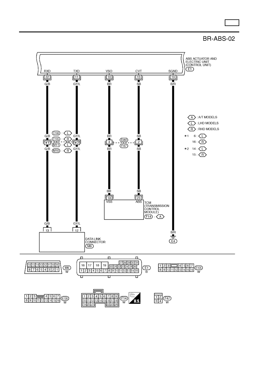
ABS
Wiring Diagram — ABS — (Cont’d)
BR-53