Nissan Pathfinder (2008 year). Manual - part 608
TM-206
< ON-VEHICLE REPAIR >
CONTROL VALVE WITH TCM
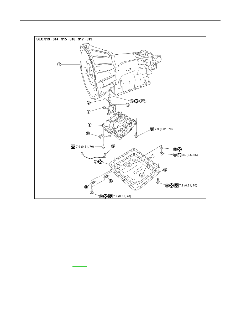
Exploded view
INFOID:0000000001724671
Removal and Installation
INFOID:0000000001724673
CONTROL VALVE WITH TCM REMOVAL AND INSTALLATION
Removal
1.
Disconnect negative battery terminal.
2.
Drain A/T fluid. Refer to
.
3.
Disconnect A/T assembly harness connector.
1.
Transmission
2.
Snap ring
3.
Sub-harness
4.
Control valve with TCM
5.
Bracket
6.
A/T fluid temperature sensor 2
7.
Oil pan gasket
8.
Clips
9.
Oil pan bolt
10. Oil pan
11.
Magnet
12. Drain plug
13. Drain plug gasket
14. Terminal cord assembly
15. O-ring
AWDIA0024ZZ