Nissan Pathfinder (2008 year). Manual - part 205


  Index      Manuals     Nissan Pathfinder (2008 year) - Service and Repair Manual


Search            copyright infringement  


Content      ..     203      204      205      206     ..


Nissan Pathfinder (2008 year). Manual - part 205


DLN-224

< COMPONENT DIAGNOSIS >

[TRANSFER: TX15B]

P1817 ACTUATOR MOTOR

4.

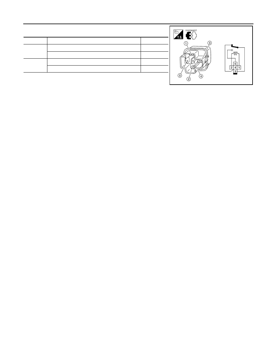
Check continuity between relay terminals 3 and 4, and 3 and 5.

5.

If the inspection results are abnormal replace the transfer shift
high or low relay.

Terminal

Condition

Continuity

3 - 4

12V direct current supply between terminals 1 and 2

No

OFF

Yes

3 - 5

12V direct current supply between terminals 1 and 2

Yes

OFF

No

LDIA0099E

P1818 ACTUATOR POSITION SWITCH

DLN-225

< COMPONENT DIAGNOSIS >

[TRANSFER: TX15B]

C

E

F

G

H

I

J

K

L

M

A

B

DLN

N

O

P

P1818 ACTUATOR POSITION SWITCH

Description

INFOID:0000000001500050

The actuator position switch detects the current actuator motor range.  DTC P1818 will set if either of the fol-
lowing occur:
• Improper signal from actuator position switch is input due to open or short circuit.
• Malfunction is detected in actuator position switch.

DTC Logic

INFOID:0000000001500051

DTC DETECTION LOGIC

DTC CONFIRMATION PROCEDURE

1.

DTC CONFIRMATION PROCEDURE

1.

Turn ignition switch ON.

2.

Perform self-diagnosis.

Is DTC P1818 detected?

YES

>> Perform diagnosis procedure. Refer to 

DLN-225, "Diagnosis Procedure"

.

NO

>> Inspection End.

Diagnosis Procedure

INFOID:0000000001500052

1.

CHECK ACTUATOR POSITION SWITCH SIGNAL

 With CONSULT-III

1.

Start engine.

2.

Depress brake pedal and stop vehicle.

3.

Set A/T selector lever to "N" position.

4.

Select “DATA MONITOR” mode for “ALL MODE AWD/4WD” with CONSULT-III.

5.

Read out the value of “SHIFT POS SW1”, “SHIFT POS SW2”, “SHIFT POS SW3”, “SHIFT POS SW4”.

 Without CONSULT-III

1.

Start engine.

2.

Depress brake pedal and stop vehicle.

3.

Set A/T selector lever to "N" position.

DTC

CONSULT-III

Diagnostic item is detected when...

Reference

[P1818]

SHIFT ACT POSI SW

• Improper signal from actuator position 

switch is input due to open or short cir-
cuit.

• Malfunction is detected in actuator po-

sition switch.

DLN-225

Monitored item

Condition

Display value

SHIFT POS SW1

4WD shift switch: 2WD and 4LO

ON

4WD shift switch: 4H

OFF

SHIFT POS SW2

4WD shift switch: 4LO

ON

4WD shift switch: 2WD and 4H

OFF

SHIFT POS SW3

4WD shift switch: 2WD and 4H

ON

4WD shift switch: 4LO

OFF

SHIFT POS SW4

4WD shift switch: 4H and 4LO

ON

4WD shift switch: 2WD

OFF

DLN-226

< COMPONENT DIAGNOSIS >

[TRANSFER: TX15B]

P1818 ACTUATOR POSITION SWITCH

4.

Check voltage between transfer control unit harness connector
terminal and ground.

Are the inspection results normal?

YES 

>> GO TO 4.

NO

>> GO TO 2.

2.

CHECK HARNESS BETWEEN TRANSFER CONTROL UNIT AND ACTUATOR POSITION SWITCH

1.

Turn ignition switch “OFF”.  (Stay for at least 5 seconds.)

2.

Disconnect transfer control unit harness connector and the transfer control device (actuator position
switch) harness connector.

3.

Check continuity between the following terminals.

-

Transfer control unit harness connector M152 terminal 10 and
transfer control device (actuator position switch) harness con-
nector F58 terminal 26.

-

Transfer control unit harness connector M152 terminal 11 and
transfer control device (actuator position switch) harness con-
nector F58 terminal 20.

-

Transfer control unit harness connector M152 terminal 12 and
transfer control device (actuator position switch) harness con-
nector F58 terminal 21.

-

Transfer control unit harness connector M152 terminal 13 and
transfer control device (actuator position switch) harness con-
nector F58 terminal 25.

Also check harness for short to ground and short to power.

Is there continuity?

YES 

>> GO TO 3.

NO

>> Repair or replace damaged parts.

3.

CHECK GROUND CIRCUIT

1.

Turn ignition switch “OFF”.  (Stay for at least 5 seconds.)

Connector

Terminal

Condition

Voltage 

(Approx.)

E142

10 - 

Ground

4WD shift switch: 2WD and 4LO

0V

4WD shift switch: 4H

Battery 
voltage

11 - 

Ground

4WD shift switch: 4LO

0V

4WD shift switch: 2WD and 4H

Battery 
voltage

12 - 

Ground

4WD shift switch: 2WD and 4H

0V

4WD shift switch: 4LO

Battery 
voltage

13 - 

Ground

4WD shift switch: 4H and 4LO

0V

4WD shift switch: 2WD

Battery 
voltage

SDIA3369E

Continuity should exist.

SDIA3370E

P1818 ACTUATOR POSITION SWITCH

DLN-227

< COMPONENT DIAGNOSIS >

[TRANSFER: TX15B]

C

E

F

G

H

I

J

K

L

M

A

B

DLN

N

O

P

2.

Check continuity between transfer control device (actuator posi-
tion switch) harness connector F58 terminal 22 and ground.

Also check harness for short to power.

Is there continuity?

YES 

>> GO TO 4.

NO

>> Repair open circuit or short to power in harness or con-

nectors.

4.

CHECK TRANSFER CONTROL UNIT

Check transfer control unit input/output signal. Refer to 

DLN-232, "Reference Value"

.

Are the inspection results normal?

YES

>> GO TO 5.

NO

>> Check transfer control unit pin terminals for damage or loose connection with harness connector.

If any items are damaged, repair or replace damaged parts.

5.

CHECK DTC

Perform the self-diagnosis, after driving a vehicle for a while.

Is DTC P1818 displayed?

YES

>> Replace transfer control device. Refer to 

DLN-270, "Removal and Installation"

.

NO

>> Inspection End.

Continuity should exist.

SDIA2815E

DLN-228

< COMPONENT DIAGNOSIS >

[TRANSFER: TX15B]

P1819 TRANSFER CONTROL DEVICE

P1819 TRANSFER CONTROL DEVICE

Description

INFOID:0000000001500055

The transfer control device integrates the actuator motor and actuator position switch.  DTC P1819 will set if
either of the following conditions exist:
• Malfunction occurs in transfer control device drive circuit.
• Malfunction is detected in transfer shut off relay 1 and transfer shut off relay 2.

DTC Logic

INFOID:0000000001500056

DTC DETECTION LOGIC

DTC CONFIRMATION PROCEDURE

1.

DTC CONFIRMATION PROCEDURE

1.

Turn ignition switch ON.

2.

Perform self-diagnosis.

Is DTC P1819 detected?

YES

>> Perform diagnosis procedure. Refer to 

DLN-228, "Diagnosis Procedure"

.

NO

>> Inspection End.

Diagnosis Procedure

INFOID:0000000001500057

1.

CHECK POWER SUPPLY 

1.

Turn ignition switch “OFF”.  (Stay for at least 5 seconds.)

2.

Disconnect transfer control unit harness connector.

3.

Check voltage between transfer control unit harness connector
terminal and ground.

4.

Turn ignition switch “ON”. (Do not start engine.)

5.

Check voltage between transfer control unit harness connector
terminals and ground.

Are the inspection results normal?

YES

>> GO TO 2.

NO

>>

Check the following. If any items are damaged, repair
or replace damaged parts.

• 10A fuse (No. 57, located in the fuse and relay box).

DTC

CONSULT-III

Diagnostic item is detected when...

Reference

[P1819]

SHIFT ACT CIR

• Malfunction is detected in transfer 

shut off relay 1 and transfer shut off re-
lay 2.

• Malfunction occurs in transfer control 

device drive circuit.

DLN-228

Connector

Terminal

Voltage (Approx.)

M152

25 - Ground

0V

M153

27 - Ground

SDIA3371E

Connector

Terminal

Voltage (Approx.)

M152

25 - Ground

Battery voltage

M153

27 - Ground

SDIA3372E

P1819 TRANSFER CONTROL DEVICE

DLN-229

< COMPONENT DIAGNOSIS >

[TRANSFER: TX15B]

C

E

F

G

H

I

J

K

L

M

A

B

DLN

N

O

P

• 40A fuse (No. J, located in the fuse and fusible link box).
• Harness for short or open between battery and transfer shut off relay 1 harness connector E156

terminal 3.

• Harness for short or open between transfer control unit harness connector M153 terminal 27

and transfer shut off relay 1 harness connector E156 terminal 5.

• Harness for short or open between ignition switch and transfer shut off relay 1 harness connec-

tor E156 terminal 1.

• Harness for short or open between transfer shut off relay 1 harness connector E156 terminal 2

and ground.

• Harness for short or open between ignition switch and transfer control unit harness connector

M152 terminal 25.

• Battery and ignition switch.
• Transfer shut off relay 1. Refer to 

DLN-203, "Component Inspection"

.

2.

CHECK GROUND CIRCUIT

1.

Turn ignition switch "OFF".

2.

Disconnect transfer control unit harness connector.

3.

Check continuity between transfer control unit harness connec-
tor M153 terminal 32 and ground.

Also check harness for short to power.

Is there continuity?

YES

>> GO TO 3.

NO

>> Repair open circuit or short to power in harness or con-

nectors.

3.

CHECK POWER SUPPLY SIGNAL

1.

Turn ignition switch “OFF”.  (Stay for at least 5 seconds.)

2.

Connect transfer control unit harness connector.

3.

Check voltage between transfer control unit harness connector
terminal and ground.

4.

Turn ignition switch “ON”. (Do not start engine.)

5.

Check voltage between transfer control unit harness connector
terminal and ground.

Are the inspection results normal?

YES

>> GO TO 4.

NO

>>

Check the following. If any items are damaged, repair
or replace damaged parts.

• Harness for short or open between battery and trans-

fer shut off relay 2 harness connector E157 terminal 1.

• Harness for short or open between transfer shut off relay 2 harness connector E157 terminal 2

and transfer control unit harness connector M153 terminal 40.

• Transfer shut off relay 2.

Continuity should exist.

SDIA2818E

Connector

Terminal

Voltage (Approx.)

M153

40 - Ground

Battery voltage

SDIA2819E

Connector

Terminal

Voltage (Approx.)

M153

40 - Ground

0V

SDIA2820E

DLN-230

< COMPONENT DIAGNOSIS >

[TRANSFER: TX15B]

P1819 TRANSFER CONTROL DEVICE

4.

CHECK TRANSFER CONTROL UNIT

Check transfer control unit input/output signal. Refer to 

DLN-232, "Reference Value"

.

Are the inspection results normal?

YES

>> GO TO 5 (With CONSULT-III) or GO TO 6 (Without CONSULT-III).

NO

>> Check transfer control unit pin terminals for damage or loose connection with harness connector.

If any items are damaged, repair or replace damaged parts.

5.

PERFORM SELF-DIAGNOSIS (WITH CONSULT-III)

 With CONSULT-III

1.

Turn ignition switch “ON”. (Do not start engine.)

2.

Select “SELF-DIAG RESULTS” mode for “ALL MODE AWD/4WD” with CONSULT-III.

3.

Touch “ERASE”.

4.

Turn ignition switch “OFF” and wait at least 10 seconds.

5.

Perform the self-diagnosis again.

Is the “SHIFT ACT CIR [P1819]” displayed?

YES

>> Replace transfer control unit. Refer to 

DLN-270, "Removal and Installation"

.

NO

>> Inspection End.

6.

PERFORM SELF-DIAGNOSIS (WITHOUT CONSULT-III)

 Without CONSULT-III

1.

Perform the self-diagnosis and then erase self-diagnostic results. Refer to 

DLN-197, "CONSULT-III Func-

tion (ALL MODE AWD/4WD)"

.

2.

Perform the self-diagnosis again.

Do the self-diagnostic results indicate transfer control device?

YES

>> Replace transfer control unit. Refer to 

DLN-270, "Removal and Installation"

.

NO

>> Inspection End.

P1820 ENGINE SPEED SIGNAL

DLN-231

< COMPONENT DIAGNOSIS >

[TRANSFER: TX15B]

C

E

F

G

H

I

J

K

L

M

A

B

DLN

N

O

P

P1820 ENGINE SPEED SIGNAL

Description

INFOID:0000000001500060

The ECM transmits the engine speed signal via CAN communication to the transfer control unit.  DTC P1820
will set when either of the following occur:
• Malfunction is detected in engine speed signal that is output from the ECM.
• Improper signal is input while driving.

DTC Logic

INFOID:0000000001500061

DTC DETECTION LOGIC

DTC CONFIRMATION PROCEDURE

1.

DTC CONFIRMATION PROCEDURE

1.

Turn ignition switch ON.

2.

Perform self-diagnosis.

Is DTC P1820 detected?

YES

>> Perform diagnosis procedure. Refer to 

DLN-231, "Diagnosis Procedure"

.

NO

>> Inspection End.

Diagnosis Procedure

INFOID:0000000001500062

1.

CHECK DTC WITH ECM

Perform self-diagnosis with ECM. Refer to 

EC-74, "CONSULT-III Function (ENGINE)"

.

Is any malfunction detected by self-diagnosis?

YES

>> Check the malfunctioning system.

NO

>> GO TO 2.

2.

CHECK TRANSFER CONTROL UNIT

Check transfer control unit input/output signal. Refer to 

DLN-232, "Reference Value"

.

Are the inspection results normal?

YES

>> GO TO 3.

NO

>> Check transfer control unit pin terminals for damage or loose connection with harness connector.

If any items are damaged, repair or replace damaged parts.

3.

CHECK DTC

Perform the self-diagnosis, after driving a vehicle for a while.

Is DTC P1820 displayed?

YES

>> Perform self-diagnosis with ECM again.

NO

>> Inspection End.

DTC

CONSULT-III

Diagnostic item is detected when...

Reference

[P1820]

ENGINE SPEED SIG

• Malfunction is detected in engine 

speed signal that is output from ECM 
through CAN communication.

• Improper signal is input while driving.

DLN-231


Content      ..     203      204      205      206     ..