Nissan Pathfinder (2008 year). Manual - part 203
DLN-208
< COMPONENT DIAGNOSIS >
[TRANSFER: TX15B]
P1810 4 LO SWITCH
P1810 4 LO SWITCH
Description
INFOID:0000000001500025
The 4LO switch detects that the transfer case is in 4LO range. DTC P1810 will set when an improper signal
from the 4LO switch is input due to an open or short circuit.
DTC Logic
INFOID:0000000001500026
DTC DETECTION LOGIC
DTC CONFIRMATION PROCEDURE
1.
DTC CONFIRMATION PROCEDURE
1.
Turn ignition switch ON.
2.
Perform self-diagnosis.
Is DTC P1810 displayed?
YES
>> Perform diagnosis procedure. Refer to
DLN-208, "Diagnosis Procedure"
.
NO
>> Inspection End.
Diagnosis Procedure
INFOID:0000000001500027
1.
CHECK 4LO POSITION SWITCH SIGNAL
With CONSULT-III
1.
Start engine.
2.
Select “DATA MONITOR” mode for “ALL MODE AWD/4WD” with CONSULT-III.
3.
Read out the value of “4L POSI SW”.
Without CONSULT-III
1.
Start engine.
2.
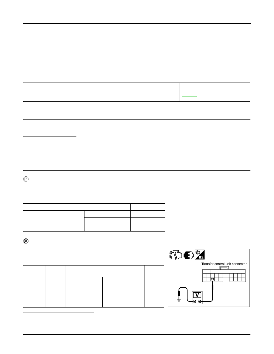
Check voltage between transfer control unit harness connector
terminal and ground.
Are the inspection results normal?
YES
>> GO TO 5.
NO
>> GO TO 2.
2.
CHECK HARNESS BETWEEN TRANSFER CONTROL UNIT AND 4LO SWITCH
1.
Turn ignition switch “OFF”. (Stay for at least 5 seconds.)
DTC
CONSULT-III
Diagnostic item is detected when...
Reference
[P1810]
4L POSI SW TF
Improper signal from 4LO switch is input
due to open or short circuit.
Condition
Display value
• Vehicle stopped
• Engine running
• A/T selector lever “N” position
• Brake pedal depressed
4WD shift switch: 4LO
ON
Except the above
OFF
Connector
Terminal
Condition
Voltage
(Approx.)
E142
24 -
Ground
• Vehicle stopped
• Engine running
• A/T selector lever
“N” position
• Brake pedal de-
pressed
4WD shift switch: 4LO
0V
Except the above
Battery
voltage
SDIA3363E