Nissan Pathfinder (2008 year). Manual - part 194


  Index      Manuals     Nissan Pathfinder (2008 year) - Service and Repair Manual


Search            copyright infringement  


Content      ..     192      193      194      195     ..


Nissan Pathfinder (2008 year). Manual - part 194


DLN-136

< ON-VEHICLE REPAIR >

[TRANSFER: ATX14B]

FRONT OIL SEAL

FRONT OIL SEAL

Removal and Installation

INFOID:0000000001282261

REMOVAL

1.

Partially drain the transfer fluid. Refer to 

DLN-132

.

2.

Remove the front propeller shaft. Refer to 

DLN-308, "Removal and Installation"

.

3.

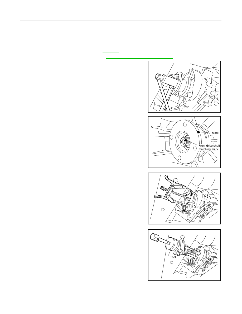
Remove the companion flange self-lock nut using Tool.

4.

Put a matching mark on top of the front drive shaft in line with
the mark on the companion flange.

CAUTION:

Use paint to make the matching mark on the front drive
shaft. Do not damage the front drive shaft.

5.

Remove the companion flange using suitable tool.

6.

Remove the front oil seal from the front case using Tool.

CAUTION:

Do not damage front case.

INSTALLATION

Tool number

: KV40104000 (

)

SDIA2657E

SDIA2658E

WDIA0193E

Tool number

: ST33290001 (J-34286)

LDIA0144E

FRONT OIL SEAL

DLN-137

< ON-VEHICLE REPAIR >

[TRANSFER: ATX14B]

C

E

F

G

H

I

J

K

L

M

A

B

DLN

N

O

P

1.

Install the new front oil seal until it is flush with the end face of
the front case using Tool.

CAUTION:

• Do not reuse oil seal.
• Apply petroleum jelly to oil seal.

2.

Align the matching mark of the front drive shaft with the match-
ing mark of the companion flange, then install the companion
flange.

3.

Install the new self-lock nut. Tighten to the specified torque
using Tool. Refer to 

DLN-149, "Disassembly and Assembly"

.

CAUTION:

Do not reuse self-lock nut.

4.

Install the front propeller shaft. Refer to 

DLN-308, "Removal and

Installation"

.

5.

Refill the transfer with fluid and check for fluid leakage and fluid
level. Refer to 

DLN-132

.

Tool number

: KV38100500 (

)

SDIA2662E

SDIA2658E

Tool number

: KV40104000 (

)

LDIA0147E

DLN-138

< ON-VEHICLE REPAIR >

[TRANSFER: ATX14B]

REAR OIL SEAL

REAR OIL SEAL

Removal and Installation

INFOID:0000000001282262

REMOVAL

1.

Partially drain the transfer fluid. Refer to 

DLN-132

.

2.

Remove the rear propeller shaft. Refer to 

DLN-316, "Removal and Installation"

.

3.

Remove the dust cover from the rear case.

CAUTION:

Do not damage the rear case.

4.

Remove the rear oil seal from the rear case using Tool.

CAUTION:

Do not damage the rear case.

INSTALLATION

1.

Install the new rear oil seal until it is flush with the end face of the
rear case using Tool.

CAUTION:

• Do not reuse oil seal.
• Apply petroleum jelly to oil seal.

2.

Apply petroleum jelly to the circumference of the new dust cover.
Position the new dust cover using the identification mark as
shown.

CAUTION:

• Do not reuse dust cover.
• Position the identification mark at the position shown.

WDIA0127E

Tool number

: ST33290001 (J-34286)

LDIA0139E

Tool number

: ST30720000 (J-25405)

LDIA0140E

SDIA3436E

REAR OIL SEAL

DLN-139

< ON-VEHICLE REPAIR >

[TRANSFER: ATX14B]

C

E

F

G

H

I

J

K

L

M

A

B

DLN

N

O

P

3.

Install the new dust cover to the rear case using Tool.

CAUTION:

• Do not reuse dust cover.
• Apply petroleum jelly to dust cover.

4.

Install the rear propeller shaft. Refer to 

DLN-316, "Removal and

Installation"

.

5.

Refill the transfer with fluid and check for fluid leakage and fluid
level. Refer to 

DLN-132

.

Tool number

: KV40105310 (

)

PDIA0116E

DLN-140

< ON-VEHICLE REPAIR >

[TRANSFER: ATX14B]

SIDE OIL SEAL

SIDE OIL SEAL

Removal and Installation

INFOID:0000000001282263

REMOVAL

1.

Remove the front propeller shaft. Refer to 

DLN-308, "Removal and Installation"

.

2.

Remove the companion flange. Refer to 

DLN-288, "Disassembly and Assembly"

.

3.

Remove the transfer control device from the transfer assembly. Refer to 

DLN-275, "Removal and Installa-

tion"

.

4.

Remove the side oil seal using suitable tool.

CAUTION:

Do not damage shift cross.

INSTALLATION

1.

Install the new side oil seal until it is flush with the end face of
case using Tool.

CAUTION:

• Do not reuse oil seal.
• Apply petroleum jelly to oil seal.

2.

Install the transfer control device to the transfer assembly. Refer
to 

DLN-275, "Removal and Installation"

.

3.

Install the companion flange. Refer to 

DLN-288, "Disassembly

and Assembly"

.

4.

Install the front propeller shaft. Refer to 

DLN-308, "Removal and Installation"

.

SDIA2666E

Tool number

: ST22360002 (J-25679-01)

SDIA2665E

TRANSFER CONTROL DEVICE

DLN-141

< ON-VEHICLE REPAIR >

[TRANSFER: ATX14B]

C

E

F

G

H

I

J

K

L

M

A

B

DLN

N

O

P

TRANSFER CONTROL DEVICE

Removal and Installation

INFOID:0000000001282264

CAUTION:

• Change vehicle state to 2WD, and then remove and install transfer control device.
• Check 4WD shift indicator after installation. Refer to 

DLN-125, "Precaution for Transfer Assembly

and Transfer Control Unit Replacement"

.

1.

Shift lever

2.

Actuator

SDIA2654E

DLN-142

< ON-VEHICLE REPAIR >

[TRANSFER: ATX14B]

AIR BREATHER HOSE

AIR BREATHER HOSE

Removal and Installation

INFOID:0000000001282265

VQ40DE

CAUTION:

• Make sure there are no pinched or restricted areas on each air breather hose caused by folding or

bending when installing it.

• Install each air breather hose into the breather tube (metal

connector) until the hose end reaches the end of the curve
section. Set each air breather hose with paint mark facing
upward. 

• Install actuator/transfer motor air breather hose and transfer

air breather hose on clip A with the paint mark facing upward.

SDIA3339E

1.

Breather tube

2.

Clip A

3.

Clip B

4.

Clip C

5.

Clip D

6.

Clip E

7.

Actuator

8.

Air breather hose clamp

9.

Clip F

10. Transfer motor

11.

Breather tube (transfer)

SDIA3340E

SDIA3342E

AIR BREATHER HOSE

DLN-143

< ON-VEHICLE REPAIR >

[TRANSFER: ATX14B]

C

E

F

G

H

I

J

K

L

M

A

B

DLN

N

O

P

• Install clip C on actuator/transfer motor air breather hose and

transfer air breather hose with the paint mark matched.

• Install actuator/transfer motor air breather hose and transfer

air breather hose on clip D and clip E with the paint mark fac-
ing upward.

• Install the actuator air breather hose into the actuator (case

connector) until the hose end reaches the base of the tube.
Set actuator air breather hose with paint mark facing leftward.

• Install clip F on transfer motor air (control device) breather

hose and transfer air breather hose with the paint mark
matched.

SDIA3343E

SDIA3344E

SDIA3226E

SDIA3345E


Content      ..     192      193      194      195     ..