Nissan Pathfinder (2008 year). Manual - part 129
ENGINE COOLING FAN
CO-21
< ON-VEHICLE REPAIR >
[VQ40DE]
C
D
E
F
G
H
I
J
K
L
M
A
CO
N
P
O
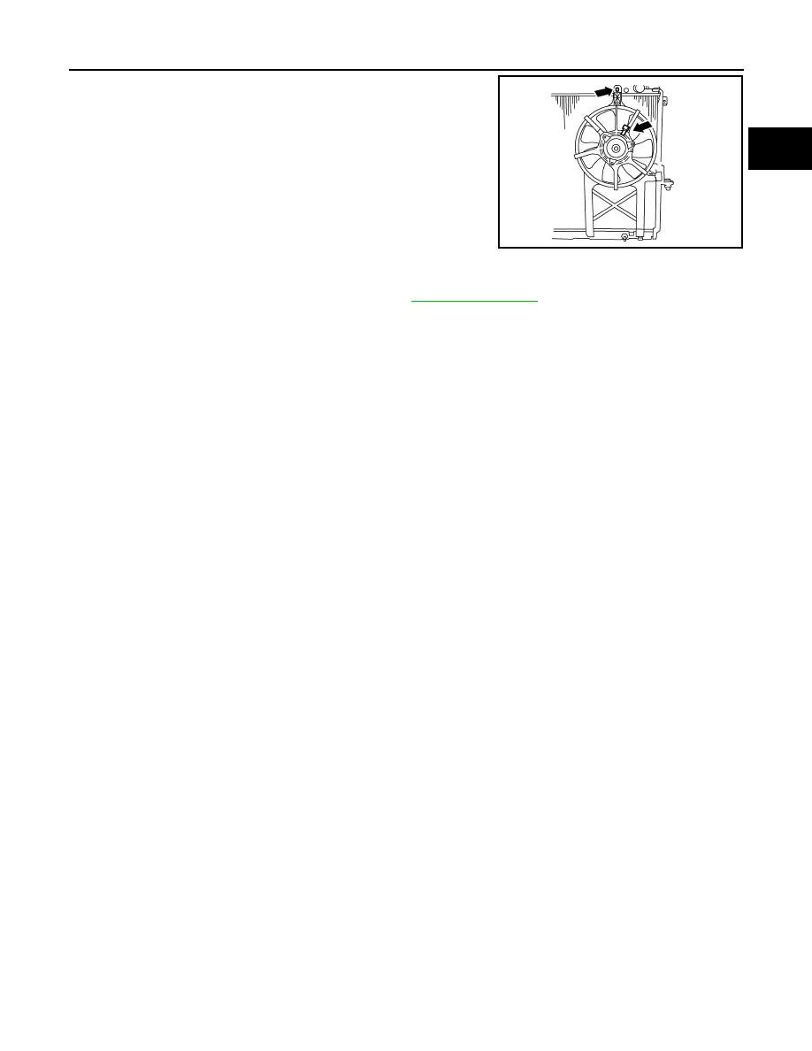
8.
Disconnect harness connector from fan motor.
9.
Remove the bolt and remove the fan grille and motor assembly.
INSTALLATION
Installation is in the reverse order of removal.
• Cooling fan is controlled by ECM. For details, refer to
.
AWBIA0148ZZ