Nissan Pathfinder (2008 year). Manual - part 128


  Index      Manuals     Nissan Pathfinder (2008 year) - Service and Repair Manual


Search            copyright infringement  


Content      ..     126      127      128      129     ..


Nissan Pathfinder (2008 year). Manual - part 128


ENGINE COOLANT

CO-13

< ON-VEHICLE MAINTENANCE >

[VQ40DE]

C

D

E

F

G

H

I

J

K

L

M

A

CO

N

P

O

4.

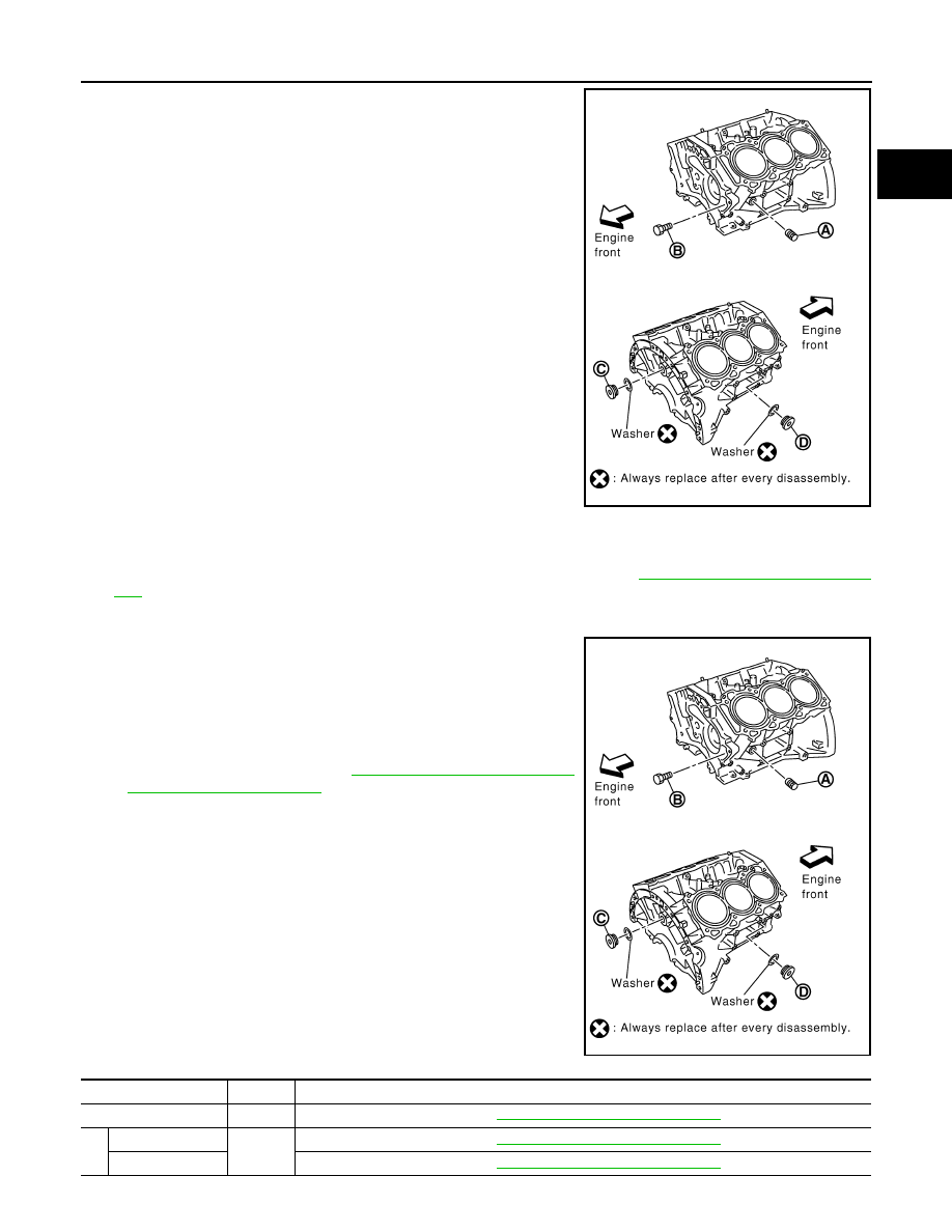
When draining all of the coolant in the system for engine
removal or repair, it is necessary to drain the cylinder block.
Remove the cylinder block drain plugs (A), (B), (C), (D) and
block heater if equipped, to drain the cylinder block as shown.
NOTE:
For Canada, the (D) cylinder block drain plug as shown, is not a
cylinder block drain plug but a block heater.

5.

Remove the reservoir tank to drain the engine coolant, then clean the reservoir tank before installing it.

6.

Check the drained coolant for contaminants such as rust, corrosion or discoloration.
If the coolant is contaminated, flush the engine cooling system. Refer to 

CO-12, "Changing Engine Cool-

ant"

.

REFILLING ENGINE COOLANT

1.

Close the radiator drain plug. Install the reservoir tank, cylinder
block drain plugs (A), (B), (C), (D) and block heater if equipped,
if removed for a total system drain or for engine removal or
repair.
• The radiator must be completely empty of coolant and water.
• Apply sealant to the threads of the cylinder block drain plugs

(A), (B), (C), (D). Use Genuine High Performance Thread
Sealant or equivalent. Refer to 

GI-26, "Recommended Chemi-

cal Products and Sealants"

.

Block Plug and Block Heater Installation

WLIA0020E

WLIA0020E

Part

Washer

Tightening Torque

A

No

Refer to 

EM-106, "Disassembly and Assembly"

.

B

Reuse

No

Refer to 

EM-106, "Disassembly and Assembly"

.

New

Refer to 

EM-106, "Disassembly and Assembly"

.

CO-14

< ON-VEHICLE MAINTENANCE >

[VQ40DE]

ENGINE COOLANT

2.

Set the vehicle heater controls to the full HOT and heater ON position. Turn the vehicle ignition ON with
the engine OFF as necessary to activate the heater mode.

3.

Remove the vented reservoir cap and replace it with a non-vented reservoir cap before filling the cooling
system.

4.

Install the Tool by installing the radiator cap adapter onto the
radiator neck opening. Then attach the gauge body assembly
with the refill tube and the venturi assembly to the radiator cap
adapter.

5.

Insert the refill hose into the coolant mixture container that is
placed at floor level. Make sure the ball valve is in the closed
position. 
• Use recommended coolant or equivalent.

Refer to 

MA-10, "Fluids and Lubricants"

.

6.

Install an air hose to the venturi assembly, the air pressure must
be within specification. 

CAUTION:

The compressed air supply must be equipped with an air
dryer.

7.

The vacuum gauge will begin to rise and there will be an audible hissing noise. During this process open
the ball valve on the refill hose slightly. Coolant will be visible rising in the refill hose. Once the refill hose is
full of coolant, close the ball valve. This will purge any air trapped in the refill hose.

8.

Continue to draw the vacuum until the gauge reaches 28 inches
of vacuum. The gauge may not reach 28 inches in high altitude
locations, use the vacuum specifications based on the altitude
above sea level.

9.

When the vacuum gauge has reached the specified amount, disconnect the air hose and wait 20 seconds
to see if the system loses any vacuum. If the vacuum level drops, perform any necessary repairs to the
system and repeat steps 6 - 8 to bring the vacuum to the specified amount. Recheck for any leaks. 

10. Place the coolant container (with the refill hose inserted) at the same level as the top of the radiator. Then

open the ball valve on the refill hose so the coolant will be drawn up to fill the cooling system. The cooling
system is full when the vacuum gauge reads zero.

CAUTION:

Do not allow the coolant container to get too low when filling, to avoid air from being drawn into
the cooling system. 

C

Yes

Refer to 

EM-106, "Disassembly and Assembly"

.

D

Plug

Yes

Refer to 

EM-106, "Disassembly and Assembly"

.

Block heater

Refer to 

EM-106, "Disassembly and Assembly"

.

Part

Washer

Tightening Torque

Tool number

: KV991J0070 (J-45695)

Cooling system capacity 
(with reservoir)

: Refer to 

MA-10, "Fluids 

and Lubricants"

.

Compressed air 
supply pressure

: 5.7 - 8.5 kPa (5.6 - 8.4 kg/cm

2

80 - 120 psi)

LLIA0058E

Altitude above sea level

Vacuum gauge reading

0 - 100 m (328 ft)

: 28 inches of vacuum

300 m (984 ft)

: 27 inches of vacuum

500 m (1,641 ft)

: 26 inches of vacuum

1,000 m (3,281 ft)

: 24 - 25 inches of vacuum

LLIA0057E

ENGINE COOLANT

CO-15

< ON-VEHICLE MAINTENANCE >

[VQ40DE]

C

D

E

F

G

H

I

J

K

L

M

A

CO

N

P

O

11. Remove the Tool from the radiator neck opening and install the radiator cap.

12. Remove the non-vented reservoir cap.
13. Fill the cooling system reservoir tank to the specified level. Run the engine to warm up the cooling system

and top up the system as necessary before installing the vented reservoir cap.

FLUSHING COOLING SYSTEM

1.

Drain the water from the engine cooling system. Refer to 

CO-12, "Changing Engine Coolant"

.

2.

Fill the radiator and the reservoir tank (to the “MAX” line), with water. Reinstall the radiator cap and leave
the vented reservoir cap off.

3.

Run the engine until it reaches normal operating temperature.

4.

Press the engine accelerator two or three times under no-load.

5.

Stop the engine and wait until it cools down.

6.

Drain the water from the engine cooling system. Refer to 

CO-12, "Changing Engine Coolant"

.

7.

Repeat steps 2 through 6 until clear water begins to drain from the radiator.

CO-16

< ON-VEHICLE REPAIR >

[VQ40DE]

RADIATOR

ON-VEHICLE REPAIR

RADIATOR

Components

INFOID:0000000001679758

Removal and Installation

INFOID:0000000001282193

WARNING:

Do not remove radiator cap when engine is hot. Serious burns could occur from high-pressure engine
coolant escaping from radiator. Wrap a thick cloth around the cap. Slowly turn it a quarter of a turn to
release built-up pressure. Carefully remove radiator cap by turning it all the way.

REMOVAL

1.

Remove air dam using power tool.

2.

Remove engine undercover using power tool.

3.

Drain engine coolant from radiator. Refer to 

CO-11

.

CAUTION:

• Perform this step when engine is cold.

1.

Radiator mounting bracket

2.

Mounting rubber (upper)

3.

Radiator cap

4.

Radiator

5.

Mounting rubber (lower)

6.

A/T fluid cooler hose

7.

A/T fluid cooler hose

8.

O-ring

9.

Drain plug

10. Cooling fan assembly

11.

Radiator shroud (upper)

12. Radiator hose (lower)

13. Radiator shroud (lower)

14. Reservoir tank hose

15. Reservoir tank cap

16. Reservoir tank

17. Water hose

18. Radiator hose (upper)

A.

To heater return tube

B.

To water pipe

C.

To A/T cooler tube

D.

To water inlet and thermostat assembly

Vehicle front

PBIC3861E

RADIATOR

CO-17

< ON-VEHICLE REPAIR >

[VQ40DE]

C

D

E

F

G

H

I

J

K

L

M

A

CO

N

P

O

• Do not spill engine coolant on drive belts.

4.

Remove air duct and air cleaner case assembly. Refer to 

EM-25, "Removal and Installation"

.

5.

Remove reservoir tank hose.

6.

Remove radiator hoses (upper and lower).

CAUTION:

Be careful not to allow engine coolant to contact drive belts.

7.

Disconnect A/T fluid cooler hoses.
• Install blind plug to avoid leakage of A/T fluid.

8.

Remove radiator shroud (lower).

9.

Remove radiator shroud (upper).

10. Remove radiator cooling fan assembly. Refer to 

CO-19

.

11. Remove the radiator mounting bracket bolts.

12. Remove the two A/C condenser bolts.

13. Remove radiator as follows:

CAUTION:

Do not damage or scratch A/C condenser and radiator core when removing.

a.

With lifting and pulling radiator in a rear direction, disassemble
mounting rubber (lower) from radiator core support center.

CAUTION:

Because A/C condenser is attached to the front-lower por-
tion of radiator, moving it in the rear direction should be at a
minimum.

LBIA0419E

LBIA0421E

PBIC1936E

CO-18

< ON-VEHICLE REPAIR >

[VQ40DE]

RADIATOR

b.

Lift A/C condenser up and remove radiator after disengaging the
fitting as front-bottom surface.

CAUTION:

Lifting A/C condenser should be minimum to prevent a load
to A/C piping.

c.

After removing radiator, put A/C condenser on radiator core sup-
port center to prevent a load to A/C piping, and temporarily fix it
with rope or similar means.

INSTALLATION

Installation is in the reverse order of removal.

INSPECTION AFTER INSTALLATION

• Check for leaks of engine coolant. Refer to 

CO-11, "System Inspection"

.

• Start and warm up engine. Visually check there are no leaks of engine coolant and A/T fluid.

Checking Radiator

INFOID:0000000001316522

Check radiator for mud or clogging. If necessary, clean radiator as follows.

CAUTION:

• Be careful not to bend or damage the radiator fins.
• When radiator is cleaned without removal, remove all surrounding parts such as cooling fan, radia-

tor shroud and horns. Then tape the harness and electrical connectors to prevent water from enter-
ing.

1.

Apply water by hose to the back side of the radiator core vertically downward.

2.

Apply water again to all radiator core surfaces.

3.

Stop washing when dirt and debris no longer flow out from the radiator.

4.

Blow air into the back side of radiator core vertically downward.
• Use compressed air lower than 490 kPa (5 kg/cm

2

, 71 psi) and keep distance more than 30 cm (11.8 in). 

5.

 Blow air again into all the radiator core surfaces until no water sprays out.

PBIC1054E

ENGINE COOLING FAN

CO-19

< ON-VEHICLE REPAIR >

[VQ40DE]

C

D

E

F

G

H

I

J

K

L

M

A

CO

N

P

O

ENGINE COOLING FAN

Removal and Installation (Crankshaft driven type)

INFOID:0000000001282194

REMOVAL

1.

Remove air dam using power tool.

2.

Remove engine front undercover using power tool.

3.

Partially drain engine coolant from radiator. Refer to 

CO-11

.

CAUTION:

• Perform this step when engine is cold.
• Do not spill engine coolant on drive belts.

4.

Remove air duct. Refer to .

EM-25, "Removal and Installation"

5.

Remove reservoir tank hose from shroud.

6.

Removal radiator hose (upper) from radiator.

CAUTION:

Be careful not to allow engine coolant to contact drive belts.

7.

Release the radiator shroud (lower) (2) from the radiator shroud
(upper) (1) and position aside. 
• Release the tabs, pull radiator shroud (lower) (2) rearwards

and down.

8.

Remove the radiator shroud (upper) bolts and remove the radiator shroud (upper). Refer to 

CO-16, "Com-

ponents"

.

9.

Remove the drive belt. Refer to 

EM-13, "Removal and Installation"

.

10. Remove the engine cooling fan.

INSPECTION AFTER REMOVAL

Fan Coupling

1.

Cooling fan

2.

Fan coupling

3.

Fan bracket

4.

Cooling fan pulley

WBIA0726E

ALBIA0470ZZ

CO-20

< ON-VEHICLE REPAIR >

[VQ40DE]

ENGINE COOLING FAN

Inspect fan coupling for oil leakage and bimetal conditions. 

Fan Bracket

• Visually check that there is no significant looseness in the fan

bracket shaft, and that it turns smoothly by hand.

• If there are any unusual concerns, replace the fan bracket assem-

bly.

INSTALLATION

Installation is in the reverse order of removal.
• Install cooling fan with its front mark “F” facing front of engine. Refer to 

CO-19, "Removal and Installation

(Crankshaft driven type)"

.

INSPECTION AFTER INSTALLATION

• Check for leaks of the engine coolant. Refer to 

CO-11, "System Inspection"

.

• Start and warm up the engine. Visually make sure that there are no leaks of the engine coolant.

Removal and Installation (Motor driven type)

INFOID:0000000001282195

REMOVAL

1.

Remove the air dam using power tool.

2.

Remove the engine front undercover using power tool.

3.

Partially drain engine coolant from radiator. Refer to 

CO-12, "Changing Engine Coolant"

.

CAUTION:

• Perform this step when engine is cold.
• Do not spill engine coolant on drive belts.

4.

Release the radiator shroud (lower) (2) from the radiator shroud
(upper) (1) and position aside. 
• Release the tabs, pull radiator shroud (lower) (2) rearwards

and down.

5.

Remove air duct. Refer to 

EM-25, "Removal and Installation"

.

6.

Remove reservoir tank hose from radiator shroud (upper).

7.

Remove the radiator shroud (upper) bolts and remove the radiator shroud (upper). Refer to 

CO-16, "Com-

ponents"

.

SLC072

LBIA0422E

ALBIA0470ZZ


Content      ..     126      127      128      129     ..