Nissan Pathfinder (2008 year). Manual - part 84
BRAKE PIPING AND HOSE
BR-19
< REMOVAL AND INSTALLATION >
C
D
E
G
H
I
J
K
L
M
A
B
BR
N
O
P
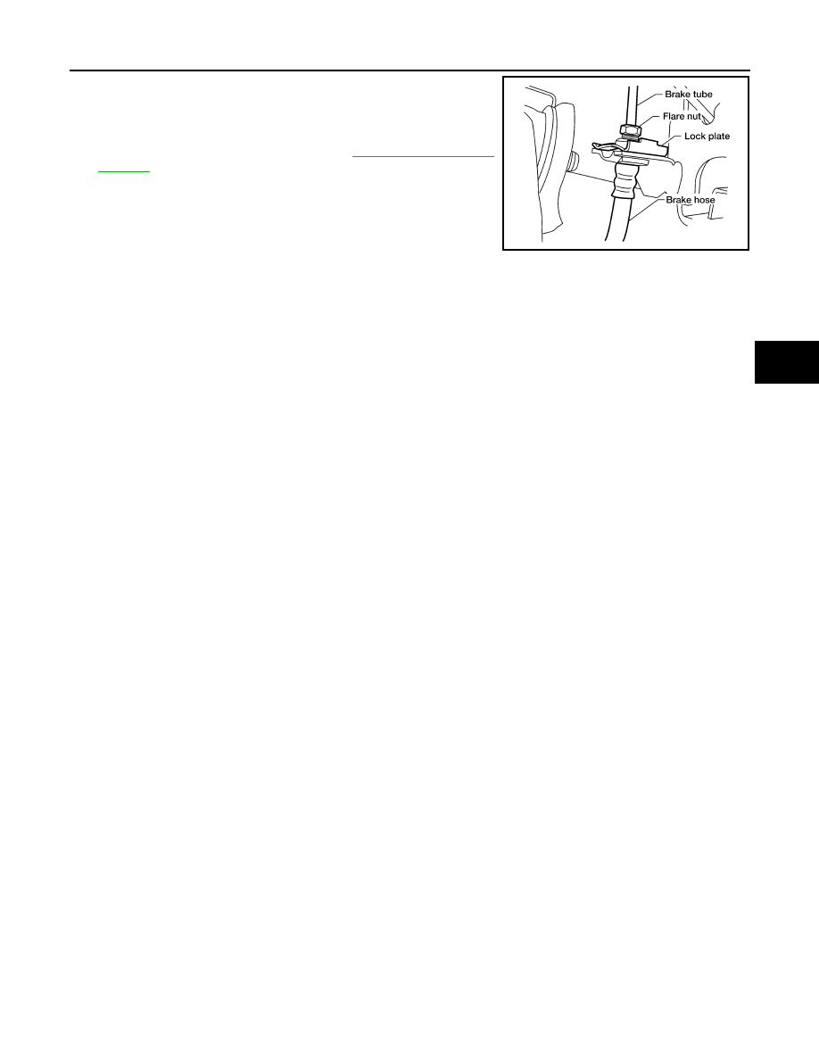
2.
Insert brake hose end through bracket, then secure it to bracket
with lock plate.
3.
Install brake tube to brake hose, then tighten flare nut to the
specified torque using a suitable tool.
4.
Refill brake fluid and bleed air. Refer to
Inspection After Installation
INFOID:0000000001297437
CAUTION:
If a leak is detected at the connections, retighten it or, if necessary, replace the damaged part.
1.
Check brake lines (tubes and hoses), and connections for fluid leaks, damage, twist, deformation, contact
with other parts, and loose connections. Replace any damaged parts.
2.
While depressing brake pedal under a force of 785 N (80 kg-f, 177 lb-f) with engine running for approxi-
mately 5 seconds, check for fluid leaks from each part.
LFIA0238E