Nissan Pathfinder (2008 year). Manual - part 25
AV-40
< FUNCTION DIAGNOSIS >
[MID AUDIO]
AUDIO SYSTEM
FUNCTION DIAGNOSIS
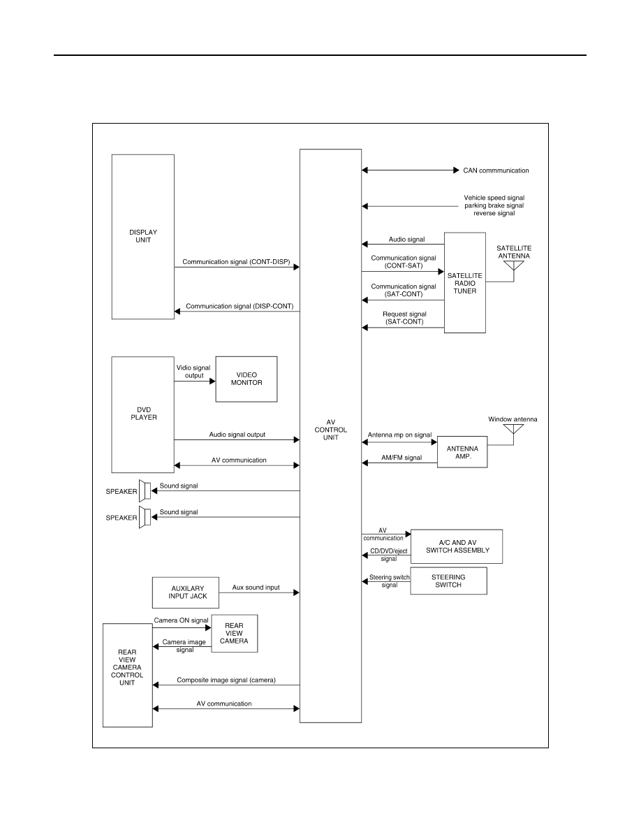
AUDIO SYSTEM
System Diagram
INFOID:0000000001450766
System Description
INFOID:0000000001450767
AUDIO SYSTEM
ALNIA0555GB
|
|
|
AV-40 < FUNCTION DIAGNOSIS > [MID AUDIO] AUDIO SYSTEM FUNCTION DIAGNOSIS AUDIO SYSTEM System Diagram INFOID:0000000001450766 System Description INFOID:0000000001450767 AUDIO SYSTEM ALNIA0555GB |