Nissan Pathfinder. Manual - part 557


  Index      Nissan     Nissan Pathfinder (2014 year) - Service and Repair Manual


Search            


Content   ..  555  556  557  558   ..


Nissan Pathfinder. Manual - part 557


TIMING CHAIN

EM-67

< REMOVAL AND INSTALLATION >

C

D

E

F

G

H

I

J

K

L

M

A

EM

N

P

O

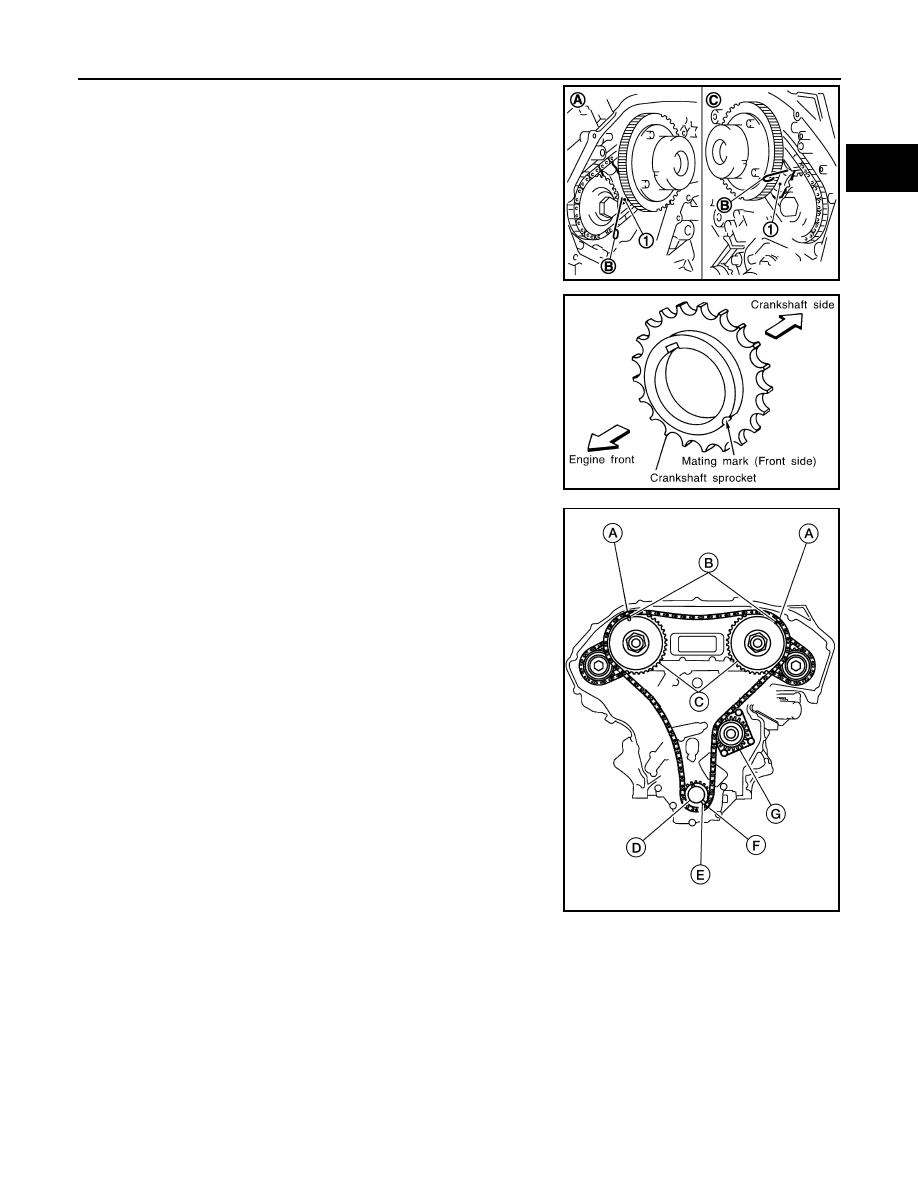
5. Pull stopper pins (B) out from timing chain tensioners (second-

ary) (1).

6. Install the crankshaft sprocket on the crankshaft.

• Make sure the mating marks on the crankshaft sprocket face

the front of the engine.

7. Install the timing chain (primary).

• Install timing chain (primary) so the mating mark (punched) (B)

on camshaft sprocket (C) is aligned with the pink link (A) on

the timing chain, while the mating mark (notched) (E) on the

crankshaft sprocket (D) is aligned with the orange one (F) on

the timing chain, as shown.

• When it is difficult to align mating marks of the timing chain

(primary) with each sprocket, gradually turn the camshaft

using a wrench on the hexagonal portion to align it with the

mating marks.

• During alignment, be careful to prevent dislocation of mating

mark alignments of the secondary timing chains.

(A)

: Bank 1

(C)

: Bank 2

JPBIA1727ZZ

SEM929E

(G)

: Water pump

WBIA0721E

EM-68

< REMOVAL AND INSTALLATION >

TIMING CHAIN

8. Install the internal chain guide (1) and slack guide (2).

CAUTION:

Do not over tighten slack guide mounting bolt (2). It is nor-

mal for a gap (A) to exist under the bolt seat when bolt is

tightened to specification.

9. Install the timing chain tensioner (primary) with the following procedure:
a. Pull plunger stopper tab (A) up (or turn lever downward) so as to

remove plunger stopper tab from the ratchet of plunger (D).

NOTE:

Plunger stopper tab and lever (C) are synchronized.

b. Push plunger into the inside of tensioner body.
c.

Hold plunger in the fully compressed position by engaging

plunger stopper tab with the tip of ratchet.

d. To secure lever, insert stopper pin (E) through hole of lever into

tensioner body hole (B).

• The lever parts and the tab are synchronized. Therefore, the

plunger will be secured under this condition.

NOTE:

Illustration shows the example of 1.2 mm (0.047 in) diameter thin screwdriver being used as the stopper

pin.

(3)

: Tension guide

JPBIA1104ZZ

(1)

: Slack guide

(3)

: Cylinder block

JPBIA0117ZZ

JPBIA0118ZZ

TIMING CHAIN

EM-69

< REMOVAL AND INSTALLATION >

C

D

E

F

G

H

I

J

K

L

M

A

EM

N

P

O

e. Install timing chain tensioner (primary) (1).

• Remove any dirt and foreign materials completely from the

back and the mount surfaces of timing chain tensioner (pri-

mary).

f.

Pull out stopper pin (A) after installing, and then release plunger.

10. Reconfirm that the matching marks on the sprockets and the timing chain have not slipped out of align-

ment.

11. Install the front timing chain case. Refer to 

EM-54, "Removal and Installation"

.

12. Install the spark plugs. Refer to 

EM-16, "Removal and Installation"

.

13. Install the intake manifold collector. Refer to 

EM-26, "Removal and Installation"

.

JPBIA0119ZZ

EM-70

< REMOVAL AND INSTALLATION >

REAR TIMING CHAIN CASE

REAR TIMING CHAIN CASE

Exploded View

INFOID:0000000009177926

Removal and Installation

INFOID:0000000009177927

CAUTION:

• After removing timing chain, do not turn the crankshaft and camshaft separately, or the valves will

strike the pistons.

• Before removing the upper oil pan, remove the crankshaft position sensor (POS).

• Be careful not to damage sensor edges.

REMOVAL

1. Remove the engine assembly. Refer to 

EM-102, "2WD : Removal and Installation"

 (2WD) or 

EM-107,

"4WD : Removal and Installation"

 (4WD).

2. Remove upper oil pan. Refer to 

EM-37, "Removal and Installation (Upper Oil Pan)"

.

3. Remove the front timing chain case. Refer to 

EM-54, "Exploded View"

.

4. Remove the timing chains (primary) and (secondary). Refer to 

EM-62, "Removal and Installation"

.

5. Remove the rear timing chain case.

CAUTION:

• Do not remove the plate metal cover for the oil passage.

• After removing the chain case, do not apply any load to

the case that might bend it.

1.

Rear timing chain case

2.

O-ring

3.

Cylinder block

AWBIA1245GB

KBIA1307E


Content   ..  555  556  557  558   ..