Nissan Pathfinder. Manual - part 382
DLK-294
< REMOVAL AND INSTALLATION >
BACK DOOR
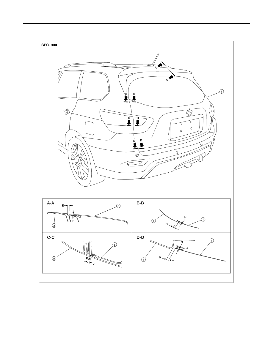
BACK DOOR ASSEMBLY : Adjustment
INFOID:0000000009175883
Check the clearance and the surface height between back door and each part by visual inspection and tactile
feel. If the clearance and the surface height are out of specification, adjust them according to the adjustment
procedure.
1.
Back door assembly
2.
Roof panel
3.
Rear spoiler
4.
Body side outer
5.
Rear combination lamp
6.
Back-up lamp
7.
Rear bumper fascia
ALKIA2968ZZ