Nissan Pathfinder. Manual - part 212
BCS
BCM
BCS-37
< ECU DIAGNOSIS INFORMATION >
[BCM]
C
D
E
F
G
H
I
J
K
L
B
A
O
P
N
14
(P)
Ground
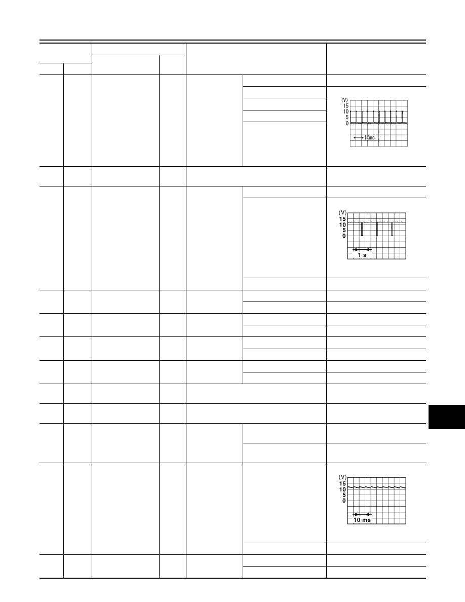
Combination switch
input 1
Input
Combination
switch
(Wiper intermit-
tent dial 4)
OFF
0V
FR WIPER HI
1.0V
INT VOLUME 1
RR WIPER INT
INT VOLUME 2
17
(R)
Ground
Auto light reference
ground
Input
Push-button ignition switch ON
0V
18
(V)
Ground Security indicator
Output Security indicator
ON
0V
Blinking
11.3V
OFF
Battery voltage
19
(Y)
Ground
Central door lock sw
signal
Input
Door lock/unlock
switch
Lock
Battery voltage
Unlock
0V
20
(W)
Ground Shift P
Input
Selector lever
P position
0V
Any position other than P
Battery voltage
21
(W)
Ground Step lamp control
Output Step lamp
ON
0V
OFF
Battery voltage
24
(SB)
Ground
Door key/c unlock sw
signal
Input
Key cylinder
switch
OFF (neutral)
5V
ON (unlock)
0V
25
(W)
Ground Brake switch fuse
Input
—
Battery voltage
26
(L)
Ground Shorting input
Input
Push-button ignition switch OFF
Battery voltage
27
(G)
Ground Brake switch lamp
Input
Stop lamp switch
OFF (brake pedal is not de-
pressed)
0V
ON (brake pedal is de-
pressed)
Battery voltage
30
(P)
Ground
Driver door lock sta-
tus
Input
Front door LH
LOCK status
11.8V
UNLOCK status
0V
32
(R)
Ground Rr def sw signal
Input
Rear window de-
fogger switch
OFF
5V
ON
0V
Terminal No.
(Wire color)
Description
Condition
Value
(Approx.)
Signal name
Input/
Output
(+)
(-)
PKIB4958J
JPMIA0014GB
JPMIA0011GB