Nissan Pathfinder. Manual - part 177
AV
U1302 CAMERA POWER VOLT
AV-535
< DTC/CIRCUIT DIAGNOSIS >
[PREMIUM AUDIO WITH NAVIGATION]
C
D
E
F
G
H
I
J
K
L
M
B
A
O
P
Is the inspection result normal?
YES
>> Replace front camera. Refer to
AV-630, "Removal and Installation"
.
NO
>> Replace around view monitor control unit. Refer to
AV-629, "Removal and Installation"
4.
CHECK REAR CAMERA POWER SUPPLY AND POWER SUPPLY GROUND CIRCUIT CONTINUITY
1. Turn ignition switch OFF.
2. Disconnect around view monitor control unit connector M96 and rear camera connector D504.
3. Check continuity between around view monitor control unit connector M96 and rear camera connector
D504.
4. Check continuity between around view monitor control unit connector M96 and ground.
Is the inspection result normal?
YES
>> GO TO 5.
NO
>> Repair or replace harness or connectors.
5.
CHECK AROUND VIEW MONITOR CONTROL UNIT VOLTAGE
1. Connect around view monitor control unit connector M96 and rear camera connector D504.
2. Turn ignition switch ON.
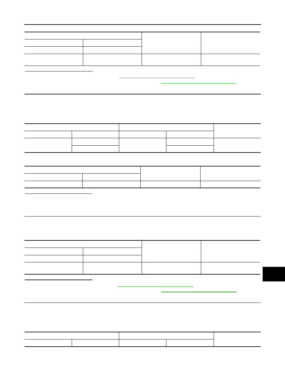
3. Check the voltage between the terminals of around view monitor control unit connector M96.
Is the inspection result normal?
YES
>> Replace rear camera. Refer to
AV-631, "Removal and Installation"
NO
>> Replace around view monitor control unit. Refer to
AV-629, "Removal and Installation"
6.
CHECK LH SIDE CAMERA POWER SUPPLY AND POWER SUPPLY GROUND CIRCUIT CONTINUITY
1. Turn ignition switch OFF.
2. Disconnect around view monitor control unit connector M96 and LH side camera connector D28.
3. Check continuity between around view monitor control unit connector M96 and LH side camera connector
D28.
Around view monitor control unit M97
Condition
Voltage
(Approx.)
(+)
(
−)
Terminal
Terminal
38
37
CAMERA switch is ON or shift
position is R.
6.0 V
Around view monitor control unit
Rear camera
Continuity
Connector
Terminal
Connector
Terminal
M96
25
D504
2
Yes
26
1
Around view monitor control unit
Ground
Continuity
Connector
Terminal
M96
25
—
No
Around view monitor control unit M96
Condition
Voltage
(Approx.)
(+)
(
−)
Terminal
Terminal
26
25
CAMERA switch is ON or shift
position is R.
6.0 V
Around view monitor control unit
LH side camera
Continuity
Connector
Terminal
Connector
Terminal