Nissan Pathfinder. Manual - part 176
 

  Index      Nissan     Nissan Pathfinder (2014 year) - Service and Repair Manual


Search            


Content   ..  174  175  176  177   ..


Nissan Pathfinder. Manual - part 176


AV

U1264 ANTENNA AMP.

AV-531

< DTC/CIRCUIT DIAGNOSIS >

[PREMIUM AUDIO WITH NAVIGATION]

C

D

E

F

G

H

I

J

K

L

M

B

A

O

P

U1264 ANTENNA AMP.

DTC Logic

INFOID:0000000009174738

Diagnosis Procedure

INFOID:0000000009174739

Regarding Wiring Diagram information, refer to 

AV-442, "Wiring Diagram"

.

1.

CHECK CONTINUITY BETWEEN AV CONTROL UNIT AND ANTENNA BASE

1. Turn ignition switch OFF.

2. Disconnect AV control unit connector M155 and antenna base connector M502.

3. Check continuity between AV control unit connector M155 and antenna base connector M502.

4. Check continuity between AV control unit connector M155 and ground.

Is the inspection result normal?

YES

>> GO TO 2.

NO

>> Repair or replace harness or connectors.

2.

CHECK AV CONTROL UNIT VOLTAGE

1. Connect AV control unit connector M155.

2. Turn ignition switch ON.

3. Check voltage between AV control unit connector M155 and ground.

Is the inspection result normal?

YES

>> Replace antenna base. Refer to 

AV-638, "Removal and Installation"

.

NO

>> Replace AV control unit. Refer to 

AV-611, "Removal and Installation"

.

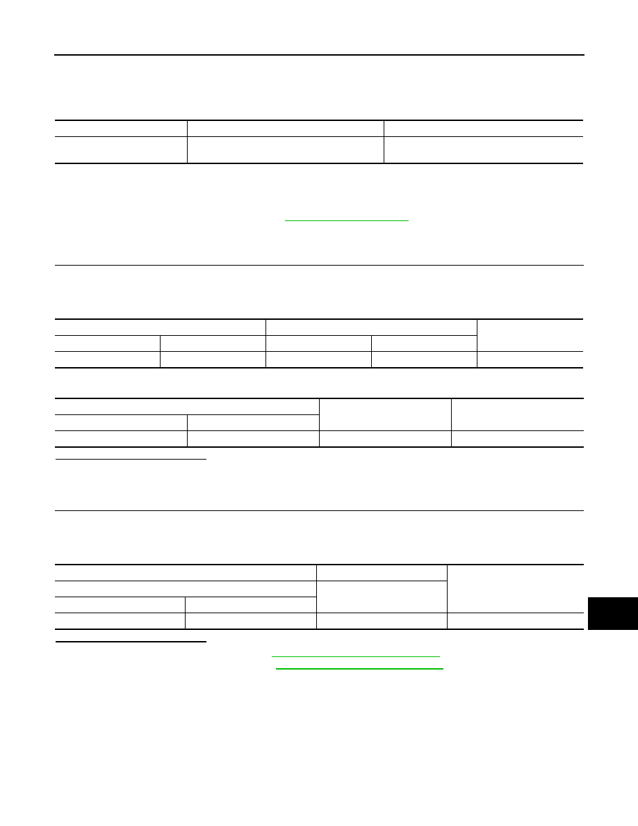
CONSULT Display

DTC Detection Condition

Possible Cause

ANTENNA AMP TERMINAL
[U1264]

Antenna amp. ON signal circuit open or short cir-
cuited.

Antenna amp. ON signal circuit between AV con-
trol unit and antenna amp.

AV control unit

Antenna base

Continuity

Connector

Terminal

Connector

Terminal

M155

126

M502

1

Yes

AV control unit

Ground

Continuity

Connector

Terminal

M155

126

No

AV control unit

Ground

Voltage

(Approx.)

(+)

(–)

Connector

Terminal

M155

126

Battery voltage

AV-532

< DTC/CIRCUIT DIAGNOSIS >

[PREMIUM AUDIO WITH NAVIGATION]

U1265 BOSE AMP.

U1265 BOSE AMP.

DTC Logic

INFOID:0000000009174740

Diagnosis Procedure

INFOID:0000000009174741

Regarding Wiring Diagram information, refer to 

AV-442, "Wiring Diagram"

.

1.

CHECK CONTINUITY BETWEEN AV CONTROL UNIT AND BOSE SPEAKER AMP.

1. Turn ignition switch OFF.

2. Disconnect AV control unit connector M161 and Bose speaker amp. connector B130.

3. Check continuity between AV control unit connector M161 and Bose speaker amp. connector B130.

4. Check continuity between AV control unit connector M161 and ground.

Is the inspection result normal?

YES

>> GO TO 2.

NO

>> Repair or replace harness or connectors.

2.

CHECK AV CONTROL UNIT VOLTAGE

1. Connect AV control unit connector M161.

2. Turn ignition switch ON.

3. Check voltage between AV control unit connector M161 and ground.

Is the inspection result normal?

YES

>> Replace Bose speaker amp. Refer to 

AV-618, "Removal and Installation"

.

NO

>> Replace AV control unit. Refer to 

AV-611, "Removal and Installation"

.

CONSULT Display

DTC Detection Condition

Possible Cause

AMP ON TERMINAL
[U1265]

BOSE amp. ON signal circuit open or short cir-
cuited.

BOSE amp. ON signal circuit between AV control 
unit and BOSE speaker amp.

AV control unit

Bose speaker amp.

Continuity

Connector

Terminal

Connector

Terminal

M161

1

B130

60

Yes

AV control unit

Ground

Continuity

Connector

Terminal

M161

1

No

AV control unit

Ground

Voltage

(Approx.)

(+)

(–)

Connector

Terminal

M161

1

Battery voltage

AV

U1300 AV COMM CIRCUIT

AV-533

< DTC/CIRCUIT DIAGNOSIS >

[PREMIUM AUDIO WITH NAVIGATION]

C

D

E

F

G

H

I

J

K

L

M

B

A

O

P

U1300 AV COMM CIRCUIT

Description

INFOID:0000000009174742

U1300 is indicated when a malfunction occurs in the communication signal of the multi AV system. Indicated

simultaneously, without fail, the malfunction of control units connected to the AV control unit through communi-

cation circuits. Determine the possible malfunction cause from the table below.

SELF DIAGNOSTIC RESULT DISPLAY ITEM

CONSULT Display

DTC Detection Condition

Possible Cause

• AV COMM CIRCUIT 

[U1300]

• SWITCH CONN 

[U1240]

When any of the following is detected:
• A/C and AV switch assembly power supply or 

ground circuit malfunction.

• AV communication circuit malfunction between AV 

control unit and A/C and AV switch assembly.

• A/C and AV switch assembly power supply and 

ground circuits.
Refer to 

AV-552, "A/C AND AV SWITCH ASSEM-

BLY : Diagnosis Procedure"

.

• AV communication circuits between AV control 

unit and A/C and AV switch assembly.

• AV COMM CIRCUIT 

[U1300]

• AMP CONN

[U124E]

When any of the following is detected:
• BOSE speaker amp. power supply or ground circuit 

malfunction.

• AV communication circuits between AV control unit 

and BOSE speaker amp. are malfunctioning.

• BOSE speaker amp. power supply and ground cir-

cuits.
Refer to 

AV-550, "BOSE AMP. : Diagnosis Proce-

dure"

.

• AV communication circuits between AV control 

unit and BOSE speaker amp.

• AV COMM CIRCUIT 

[U1300]

• VIDEO DIST CONN 

[U1246]

When any of the following is detected:
• video distributor power supply or ground circuit mal-

function.

• headrest display unit (driver seat) power supply or 

ground circuit malfunction.

• AV communication circuit malfunction between AV 

control unit and headrest display unit (driver seat).

• Video distributor power supply and ground cir-

cuits.
Refer to 

AV-553, "VIDEO DISTRIBUTOR : Diag-

nosis Procedure"

.

• Headrest display unit  (driver seat) power supply 

and ground circuits.
Refer to 

AV-554, "HEADREST DISPLAY UNIT : 

Diagnosis Procedure"

.

• AV communication circuits between AV control 

unit and headrest display unit  (driver seat).

• AV COMM CIRCUIT 

[U1300]

• AROUND CAMERA 

CONN
[U125B]

When any of the following is detected:
• around view monitor control unit power supply or 

ground circuit malfunction.

• AV communication circuit malfunction between AV 

control unit and around view monitor control unit.

• Around view monitor control unit power supply 

and ground circuits.
Refer to 

AV-554, "AROUND VIEW MONITOR 

CONTROL UNIT : Diagnosis Procedure"

.

• AV communication circuits between AV control 

unit and around view monitor control unit.

• AV COMM CIRCUIT 

[U1300]

• SWITCH CONN 

[U1240]

• AROUND CAMERA 

CONN
[U125B]

• VIDEO DIST CONN 

[U1246]

AV communication circuit malfunction between AV 
control unit and A/C and AV switch assembly.

AV communication circuits between AV control unit 
and A/C and AV switch assembly.

• AV COMM CIRCUIT 

[U1300]

• SWITCH CONN 

[U1240]

• AMP CONN

[U124E]

• AROUND CAMERA 

CONN
[U125B]

• VIDEO DIST CONN 

[U1246]

AV-534

< DTC/CIRCUIT DIAGNOSIS >

[PREMIUM AUDIO WITH NAVIGATION]

U1302 CAMERA POWER VOLT

U1302 CAMERA POWER VOLT

DTC Logic

INFOID:0000000009174743

DTC DETECTION LOGIC

Diagnosis Procedure

INFOID:0000000009174744

Regarding Wiring Diagram information, refer to 

AV-442, "Wiring Diagram"

.

1.

CHECK CAMERA DATA MONITOR

Check CAMERA IMAGE SIG, CAMERA COMM STATUS and CAMERA COMM LINE for each camera in

“DATA MONITOR” of “AVM”.
Is “OK” displayed for all cameras?

YES

>> Refer to 

GI-49, "Intermittent Incident"

.

NO-1 (Front camera)>>GO TO 2.

NO-2 (Rear camera)>>GO TO 4.

NO-3 (LH side camera)>>GO TO 6.

NO-4 (RH side camera)>>GO TO 8.

2.

CHECK FRONT CAMERA POWER SUPPLY AND POWER SUPPLY GROUND CIRCUIT CONTINUITY

1. Turn ignition switch OFF.

2. Disconnect around view monitor control unit connector M96 and camera connectors.

3. Check continuity between around view monitor control unit connector M96 and front camera connector

E226.

4. Check continuity between around view monitor control unit connector M96 and ground.

Is the inspection result normal?

YES

>> GO TO 3.

NO

>> Repair or replace harness or connectors.

3.

CHECK AROUND VIEW MONITOR CONTROL UNIT VOLTAGE

1. Connect around view monitor control unit connector M96 and front camera connector E226.

2. Turn ignition switch ON.

3. Check the voltage between the terminals of around view monitor control unit connector M96.

CONSULT Display

DTC Detection Condition

Possible Cause

CAMERA SUPPLY POWER 
SUPPLY VOLTAGE ABNOR-
MALITY
[U1302]

Short in camera power circuit.

• Harness or connectors.
• Camera.
• Around view monitor control unit.

Around view monitor control unit

Front camera

Continuity

Connector

Terminal

Connector

Terminal

M96

38

E226

1

Yes

37

2

Around view monitor control unit

Ground

Continuity

Connector

Terminal

M96

37

No


Content   ..  174  175  176  177   ..