Nissan Pathfinder. Manual - part 152


  Index      Nissan     Nissan Pathfinder (2014 year) - Service and Repair Manual


Search            


Content   ..  150  151  152  153   ..


Nissan Pathfinder. Manual - part 152


AV

HEADREST DISPLAY UNIT

AV-435

< ECU DIAGNOSIS INFORMATION >

[PREMIUM AUDIO WITH NAVIGATION]

C

D

E

F

G

H

I

J

K

L

M

B

A

O

P

HEADREST DISPLAY UNIT

Reference Value

INFOID:0000000009174673
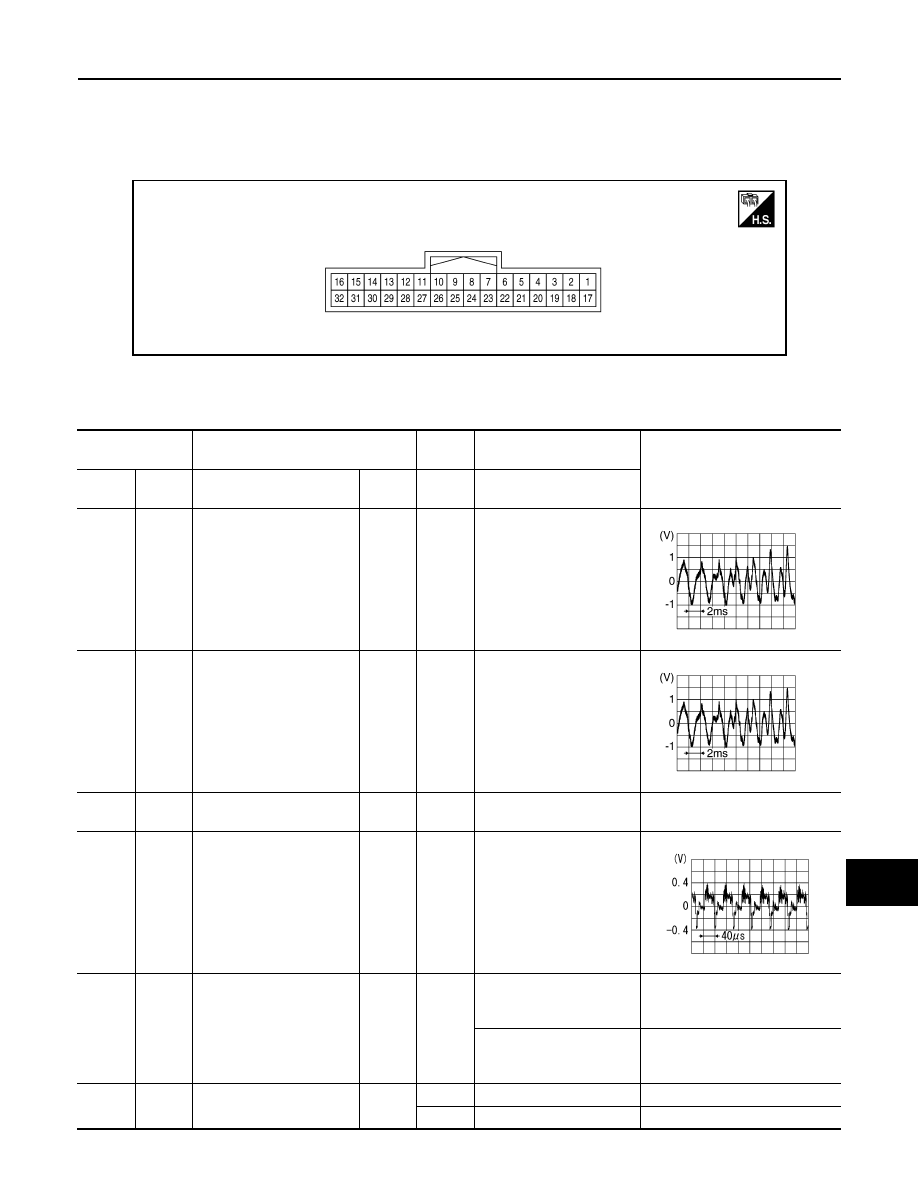
TERMINAL LAYOUT

PHYSICAL VALUES

Driver Seat

ALNIA1528ZZ

Terminal

(Wire color)

Description

Condi-

tion

Reference value

(Approx.)

+

Signal name

Input/

Output

Ignition 

switch

Operation

1

(W)

17

(B)

Headphone sound signal 
LH

Input

ON

Headphone sound output

2

(G)

18

(R)

Headphone sound signal 
RH

Input

ON

Headphone sound output

3

(LG)

Headphone sound signal 
shield

5

(Y)

Ground Composite image signal

Input

ON

When DVD, USB or front 
AUX image is displayed on 
headrest display unit

7

(W)

Ground Image switch signal

Output

ON

When DVD, USB or front 
AUX image is displayed on 
headrest display unit

0.5 V

When rear AUX image is 
displayed on headrest dis-
play unit

4.5 V

8

(G)

Ground ACC signal

Input

OFF

3.3 V

ACC

0 V

SKIB3609E

SKIB3609E

SKIB2251J

AV-436

< ECU DIAGNOSIS INFORMATION >

[PREMIUM AUDIO WITH NAVIGATION]

HEADREST DISPLAY UNIT

Passenger Seat

10

(LG)

AV communication signal 
(L)

Input/

Output

11

(P)

AV communication signal 
(H)

Input/

Output

12

(G)

Ground Ground

ON

0 V

13

(BR)

Ground Illumination

Input

OFF

Battery voltage

15

(W)

Ground Battery power supply

Input

OFF

Battery voltage

16

(W)

Ground Battery power supply

Input

OFF

Battery voltage

19

(V)

Ground AV ground

ON

0 V

20

(P)

Composite image signal 
shield

21

(G)

Ground

Composite image signal 
ground

ON

0  V

23

(Y)

Ground Control ground

ON

0 V

24

(SB)

CON  CK  B

Input/

Output

26

(R)

AV communication signal 
(L)

Input/

Output

27

(LG)

AV communication signal 
(H)

Input/

Output

29

(GR)

CON  CK  B

Input/

Output

31

(G)

Ground Ground

ON

0 V

32

(G)

Ground Ground

ON

0 V

Terminal

(Wire color)

Description

Condi-

tion

Reference value

(Approx.)

+

Signal name

Input/

Output

Ignition 

switch

Operation

AV

HEADREST DISPLAY UNIT

AV-437

< ECU DIAGNOSIS INFORMATION >

[PREMIUM AUDIO WITH NAVIGATION]

C

D

E

F

G

H

I

J

K

L

M

B

A

O

P

Terminal

(Wire color)

Description

Condi-

tion

Reference value

(Approx.)

+

Signal name

Input/

Output

Ignition 

switch

Operation

1

(W)

17

(B)

Headphone sound signal 
LH

Input

ON

Headphone sound output

2

(G)

18

(R)

Headphone sound signal 
RH

Input

ON

Headphone sound output

3

(LG)

Headphone sound signal 
shield

5

(Y)

Ground Composite image signal

Input

ON

When DVD, USB or front 
AUX image is displayed on 
headrest display unit

7

(W)

Ground Image switch signal

Output

ON

When DVD, USB or front 
AUX image is displayed on 
headrest display unit

0.5 V

When rear AUX image is 
displayed on headrest dis-
play unit

4.5 V

8

(G)

Ground ACC signal

Input

OFF

3.3 V

ACC

0 V

10

(LG)

AV communication signal 
(L)

Input/

Output

11

(P)

AV communication signal 
(H)

Input/

Output

13

(BR)

Ground Illumination

Input

OFF

Battery voltage

15

(W)

Ground Battery power supply

Input

OFF

Battery voltage

16

(W)

Ground Battery power supply

Input

OFF

Battery voltage

19

(V)

Ground AV ground

ON

0 V

20

(P)

Composite image signal 
shield

21

(G)

Ground

Composite image signal 
ground

ON

0  V

23

(Y)

Ground Control ground

ON

0 V

SKIB3609E

SKIB3609E

SKIB2251J

AV-438

< ECU DIAGNOSIS INFORMATION >

[PREMIUM AUDIO WITH NAVIGATION]

HEADREST DISPLAY UNIT

24

(SB)

CON  CK  B

Input/

Output

26

(R)

AV communication signal 
(L)

Input/

Output

27

(LG)

AV communication signal 
(H)

Input/

Output

28

(G)

Ground Ground

ON

0 V

29

(GR)

CON  CK  B

Input/

Output

31

(G)

Ground Ground

ON

0 V

32

(G)

Ground Ground

ON

0 V

Terminal

(Wire color)

Description

Condi-

tion

Reference value

(Approx.)

+

Signal name

Input/

Output

Ignition 

switch

Operation


Content   ..  150  151  152  153   ..