Murano Cross Cabriolet Z51 (2012 year). Manual - part 20


  Index      Manuals     Murano Cross Cabriolet Z51 (2012 year) - Service and Repair Manual


Search            copyright infringement  


Content      ..     18      19      20      21     ..


Murano Cross Cabriolet Z51 (2012 year). Manual - part 20


C1115 WHEEL SENSOR

BRC-53

< DTC/CIRCUIT DIAGNOSIS >

[WITH VDC]

C

D

E

G

H

I

J

K

L

M

A

B

BRC

N

O

P

14.

CHECK WHEEL SENSOR HARNESS

1.

Turn the ignition switch OFF.

2.

Disconnect ABS actuator and electric unit (control unit) harness connector.

3.

Disconnect wheel sensor harness connector.

4.

Check the continuity between ABS actuator and electric unit (control unit) harness connector and wheel
sensor harness connector. (Check the continuity when steering wheel is steered to RH and LH, or center
harness in wheel housing is moved.) 

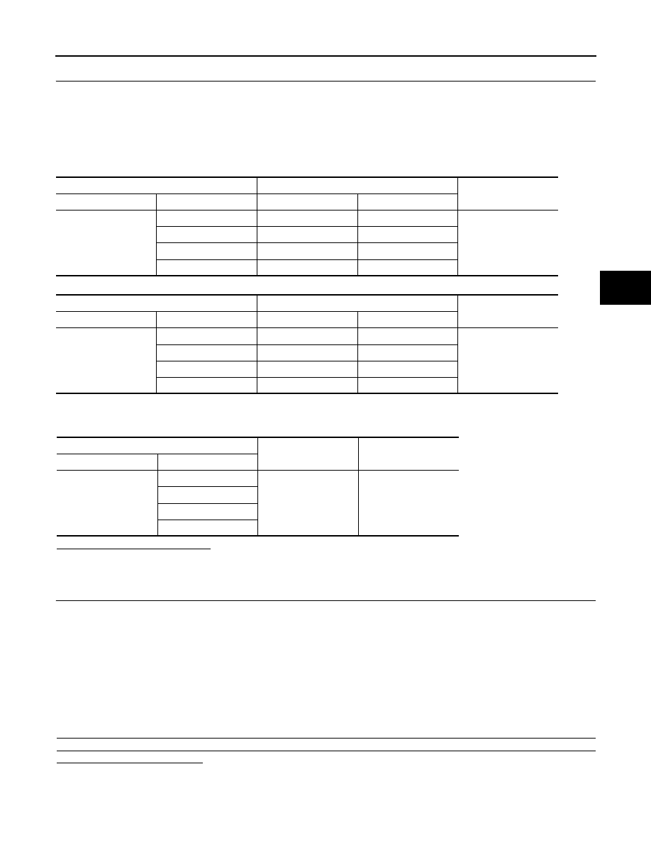
Measurement connector and terminal for power supply circuit

Measurement connector and terminal for signal circuit

5.

Check the continuity between ABS actuator and electric unit (control unit) harness connector and the
ground.

Is the inspection result normal?

YES

>> GO TO 15.

NO

>> Repair or replace error-detected parts and GO TO 15.

15.

CHECK DATA MONITOR (4)

1.

Connect ABS actuator and electric unit (control unit) harness connector.

2.

Connect wheel sensor harness connector.

3.

Erase self-diagnosis result for “ABS” with CONSULT.

4.

Turn the ignition switch OFF, and wait 10 seconds or more.

5.

Start the engine.

6.

Select “ABS” and “DATA MONITOR”, check the “FR LH SENSOR”, “FR RH SENSOR”, “RR LH SENSOR”
and “RR RH SENSOR” with CONSULT.
NOTE:
Set the “DATA MONITOR” recording speed to “10 msec”.

7.

Read a value (wheel speed) of both normal wheel sensors and error-detecting wheel sensor. 

Regarding the deference at 30 km/h (19 MPH) between the wheel speed detected by the error detecting
wheel sensor and the maximum/minimum wheel speed detected by the normal wheel sensors, is the differ-
ence within 5%, respectively?

YES

>> GO TO 16.

NO

>> GO TO 17.

ABS actuator and electric unit (control unit)

Wheel sensor

Continuity

Connector

Terminal

Connector

Terminal

E36

9

E22 (Front LH wheel)

1

Existed

5

E39 (Front RH wheel)

3

3

C5 (Rear LH wheel)

5

11

C6 (Rear RH wheel)

7

ABS actuator and electric unit (control unit)

Wheel sensor

Continuity

Connector

Terminal

Connector

Terminal

E36

8

E22 (Front LH wheel)

2

Existed

6

E39 (Front RH wheel)

4

2

C5 (Rear LH wheel)

6

12

C6 (Rear RH wheel)

8

ABS actuator and electric unit (control unit)

Continuity

Connector

Terminal

E36

9, 8

Ground

Not existed

5, 6

3, 2

11, 12

Revision: 2013 February

2012 Murano CrossCabriolet

BRC-54

< DTC/CIRCUIT DIAGNOSIS >

[WITH VDC]

C1115 WHEEL SENSOR

16.

PERFORM SELF-DIAGNOSIS (5)

1.

Drive the vehicle at approx. 30 km/h (19 MPH) or more for approx. 1 minute.

2.

Stop the vehicle.

3.

Perform self-diagnosis for “ABS” with CONSULT.

Is DTC “C1115” detected?

YES

>> GO TO 17.

NO

>> INSPECTION END

17.

REPLACE WHEEL SENSOR (2)

1.

Replace wheel sensor.

-

Front: Refer to 

BRC-98, "FRONT WHEEL SENSOR : Exploded View"

.

-

Rear: Refer to 

BRC-99, "REAR WHEEL SENSOR : Exploded View"

.

2.

Erase self-diagnosis result for “ABS” with CONSULT.

3.

Turn the ignition switch OFF, and wait 10 seconds or more.

4.

Start the engine.

5.

Select “ABS” and “DATA MONITOR”, check the “FR LH SENSOR”, “FR RH SENSOR”, “RR LH SENSOR”
and “RR RH SENSOR” with CONSULT.
NOTE:
Set the “DATA MONITOR” recording speed to “10 msec”.

6.

Read a value (wheel speed) of both normal wheel sensors and error-detecting wheel sensor. 

Regarding the deference at 30 km/h (19 MPH) between the wheel speed detected by the error detecting
wheel sensor and the maximum/minimum wheel speed detected by the normal wheel sensors, is the differ-
ence within 5%, respectively?

YES

>> GO TO 18.

NO

>> GO TO 19.

18.

PERFORM SELF-DIAGNOSIS (6)

1.

Drive the vehicle at approx. 30 km/h (19 MPH) or more for approx. 1 minute.

2.

Stop the vehicle.

3.

Perform self-diagnosis for “ABS” with CONSULT.

Is DTC “C1115” detected?

YES

>> GO TO 19.

NO

>> INSPECTION END

19.

REPLACE SENSOR ROTOR

1.

Replace sensor rotor.

-

Front: Refer to 

BRC-101, "FRONT SENSOR ROTOR : Exploded View"

.

-

Rear: Refer to 

BRC-101, "REAR SENSOR ROTOR : Exploded View"

.

2.

Erase self-diagnosis result for “ABS”.

3.

Turn the ignition switch OFF, and wait 10 seconds or more.

4.

Start the engine.

5.

Drive the vehicle at approx. 30 km/h (19 MPH) or more for approx. 1 minute.

6.

Stop the vehicle.

7.

Perform self-diagnosis for “ABS” with CONSULT.

Is DTC “C1115” detected?

YES

>> Replace ABS actuator and electric unit (control unit). Refer to 

BRC-102, "Exploded View"

.

NO

>> INSPECTION END

Revision: 2013 February

2012 Murano CrossCabriolet

C1116 STOP LAMP SWITCH

BRC-55

< DTC/CIRCUIT DIAGNOSIS >

[WITH VDC]

C

D

E

G

H

I

J

K

L

M

A

B

BRC

N

O

P

C1116 STOP LAMP SWITCH

DTC Logic

INFOID:0000000007565776

DTC DETECTION LOGIC

DTC CONFIRMATION PROCEDURE

1.

PRECONDITIONING

If “DTC CONFIRMATION PROCEDURE” has been previously conducted, always turn the ignition switch OFF
and wait at least 10 seconds before conducting the next test.

>> GO TO 2.

2.

DTC REPRODUCTION PROCEDURE

1.

Turn the ignition switch OFF to ON.

2.

Perform self-diagnosis for “ABS” with CONSULT.

Is DTC “C1116” detected?

YES

>> Proceed to diagnosis procedure. Refer to 

BRC-55, "Diagnosis Procedure"

.

NO

>> INSPECTION END

Diagnosis Procedure

INFOID:0000000007565777

1.

CHECK CONNECTOR

1.

Turn the ignition switch OFF.

2.

Disconnect ABS actuator and electric unit (control unit) harness connector.

3.

Disconnect stop lamp switch harness connector.

4.

Check the terminal for deformation, disconnection, looseness, etc.

5.

Reconnect ABS actuator and electric unit (control unit) and stop lamp switch harness connectors
securely.

6.

Start the engine.

7.

Repeat pumping brake pedal carefully several times, and perform self-diagnosis for “ABS” with CON-
SULT.

Is the inspection result normal?

YES

>> GO TO 2.

NO

>> Poor connection of connector terminal. Repair or replace error-detected parts.

2.

CHECK STOP LAMP SWITCH CLEARANCE

Check the stop lamp switch clearance. Refer to 

BR-7, "Inspection and Adjustment"

.

Is the inspection result normal?

YES

>> GO TO 3.

NO

>> Adjust stop lamp switch clearance. Refer to 

BR-7, "Inspection and Adjustment"

.

3.

CHECK STOP LAMP SWITCH

Check the stop lamp switch. Refer to 

BRC-56, "Component Inspection"

.

Is the inspection result normal?

YES

>> GO TO 4.

NO

>> Repair or replace stop lamp switch.

4.

CHECK STOP LAMP SWITCH CIRCUIT

1.

Connect ABS actuator and electric unit (control unit) harness connector.

2.

Check the voltage between ABS actuator and electric unit (control unit) harness connector and ground.

DTC

Display item

Malfunction detected condition

Possible cause

C1116

STOP LAMP SW

When a stop lamp switch signal is not input where the 
brake pedal is depressed.

• Harness or connector
• Stop lamp switch
• ABS actuator and electric unit 

(control unit)

Revision: 2013 February

2012 Murano CrossCabriolet

BRC-56

< DTC/CIRCUIT DIAGNOSIS >

[WITH VDC]

C1116 STOP LAMP SWITCH

Is the inspection result normal?

YES

>> Replace ABS actuator and electric unit (control unit). Refer to 

BRC-102, "Exploded View"

.

NO

>> Repair or replace error-detected parts.

Component Inspection

INFOID:0000000007565778

1.

CHECK STOP LAMP SWITCH

1.

Turn the ignition switch OFF.

2.

Disconnect stop lamp switch harness connector.

3.

Check the continuity between stop lamp switch connector terminals.

Is the inspection result normal?

YES

>> INSPECTION END

NO

>> Replace stop lamp switch. Refer to 

BR-18, "Exploded View"

.

ABS actuator and electric unit (control unit)

Condition

Voltage

(Approx.)

Connector

Terminal

E36

16

Ground

Brake pedal is depressed

Battery voltage

Brake pedal is released

0 V

Stop lamp switch

Condition

Continuity

Terminal

 2

Release stop lamp switch
(When brake pedal is depressed.)

Existed

Push stop lamp switch
(When brake pedal is released.)

Not existed

Revision: 2013 February

2012 Murano CrossCabriolet

C1120, C1122, C1124, C1126 IN ABS SOL

BRC-57

< DTC/CIRCUIT DIAGNOSIS >

[WITH VDC]

C

D

E

G

H

I

J

K

L

M

A

B

BRC

N

O

P

C1120, C1122, C1124, C1126 IN ABS SOL

DTC Logic

INFOID:0000000007565779

DTC DETECTION LOGIC

DTC CONFIRMATION PROCEDURE

1.

PRECONDITIONING

If “DTC CONFIRMATION PROCEDURE” has been previously conducted, always turn the ignition switch OFF
and wait at least 10 seconds before conducting the next test.

>> GO TO 2.

2.

DTC REPRODUCTION PROCEDURE

1.

Turn the ignition switch OFF to ON.

2.

Perform self-diagnosis for “ABS” with CONSULT.

Is DTC “C1120”, “C1122”, “C1124” or “C1126” detected?

YES

>> Proceed to diagnosis procedure. Refer to 

BRC-57, "Diagnosis Procedure"

.

NO

>> INSPECTION END

Diagnosis Procedure

INFOID:0000000007565780

1.

CHECK CONNECTOR

1.

Turn the ignition switch OFF.

2.

Disconnect ABS actuator and electric unit (control unit) harness connector.

3.

Check the terminal for deformation, disconnection, looseness, etc.

Is the inspection result normal?

YES

>> GO TO 2.

NO

>> Repair or replace error-detected parts.

2.

CHECK ABS IN VALVE POWER SUPPLY

1.

Check the voltage between ABS actuator and electric unit (control unit) harness connector and ground.

2.

Turn the ignition switch ON.

CAUTION:

Never start the engine.

3.

Check the voltage between ABS actuator and electric unit (control unit) harness connector and ground.

DTC

Display item

Malfunction detected condition

Possible cause

C1120

FR LH IN ABS SOL

When the control unit detects a malfunction in the front 
LH ABS IN valve circuit.

• Harness or connector
• ABS actuator and electric unit 

(control unit)

C1122

FR RH IN ABS SOL

When the control unit detects a malfunction in the front 
RH ABS IN valve circuit.

C1124

RR LH IN ABS SOL

When the control unit detects a malfunction in the rear LH 
ABS IN valve circuit.

C1126

RR RH IN ABS SOL

When the control unit detects a malfunction in the rear 
RH ABS IN valve circuit.

ABS actuator and electric unit (control unit)

Voltage

(Approx.)

Connector

Terminal

E36

1

Ground

Battery voltage

ABS actuator and electric unit (control unit)

Voltage

(Approx.)

Connector

Terminal

E36

1

Ground

Battery voltage

Revision: 2013 February

2012 Murano CrossCabriolet

BRC-58

< DTC/CIRCUIT DIAGNOSIS >

[WITH VDC]

C1120, C1122, C1124, C1126 IN ABS SOL

Is the inspection result normal?

YES

>> GO TO 4.

NO

>> GO TO 3.

3.

CHECK ABS IN VALVE POWER SUPPLY CIRCUIT

1.

Turn the ignition switch OFF.

2.

Check the 20A fusible link (#G).

3.

Check the continuity and short circuit between ABS actuator and electric unit (control unit) harness con-
nector terminal (1) and 20A fusible link (#G).

Is the inspection result normal?

YES

>> Perform trouble diagnosis for battery power supply. Refer to 

PG-11, "Wiring Diagram - BATTERY

POWER SUPPLY -"

.

NO

>> Repair or replace error-detected parts.

4.

CHECK ABS IN VALVE GROUND CIRCUIT

Check the continuity between ABS actuator and electric unit (control unit) harness connector and ground.

Is the inspection result normal?

YES

>> Replace ABS actuator and electric unit (control unit). Refer to 

BRC-102, "Exploded View"

.

NO

>> Repair or replace error-detected parts.

ABS actuator and electric unit (control unit)

Continuity

Connector

Terminal

E36

13

Ground

Existed

26

Revision: 2013 February

2012 Murano CrossCabriolet

C1121, C1123, C1125, C1127 OUT ABS SOL

BRC-59

< DTC/CIRCUIT DIAGNOSIS >

[WITH VDC]

C

D

E

G

H

I

J

K

L

M

A

B

BRC

N

O

P

C1121, C1123, C1125, C1127 OUT ABS SOL

DTC Logic

INFOID:0000000007565781

DTC DETECTION LOGIC

DTC CONFIRMATION PROCEDURE

1.

PRECONDITIONING

If “DTC CONFIRMATION PROCEDURE” has been previously conducted, always turn the ignition switch OFF
and wait at least 10 seconds before conducting the next test.

>> GO TO 2.

2.

DTC REPRODUCTION PROCEDURE

1.

Turn the ignition switch OFF to ON.

2.

Perform self-diagnosis for “ABS” with CONSULT.

Is DTC “C1121”, “C1123”, “C1125” or “C1127” detected?

YES

>> Proceed to diagnosis procedure. Refer to 

BRC-59, "Diagnosis Procedure"

.

NO

>> INSPECTION END

Diagnosis Procedure

INFOID:0000000007565782

1.

CHECK CONNECTOR

1.

Turn the ignition switch OFF.

2.

Disconnect ABS actuator and electric unit (control unit) harness connector.

3.

Check the terminal for deformation, disconnection, looseness, etc.

Is the inspection result normal?

YES

>> GO TO 2.

NO

>> Repair or replace error-detected parts.

2.

CHECK ABS OUT VALVE POWER SUPPLY

1.

Check the voltage between ABS actuator and electric unit (control unit) harness connector and ground.

2.

Turn the ignition switch ON.

CAUTION:

Never start the engine.

3.

Check the voltage between ABS actuator and electric unit (control unit) harness connector and ground.

DTC

Display item

Malfunction detected condition

Possible cause

C1121

FR LH OUT ABS SOL

When the control unit detects a malfunction in the front 
LH ABS OUT valve circuit.

• Harness or connector
• ABS actuator and electric unit 

(control unit)

C1123

FR RH OUT ABS SOL

When the control unit detects a malfunction in the front 
RH ABS OUT valve circuit.

C1125

RR LH OUT ABS SOL

When the control unit detects a malfunction in the rear LH 
ABS OUT valve circuit.

C1127

RR RH OUT ABS SOL

When the control unit detects a malfunction in the rear 
RH ABS OUT valve circuit.

ABS actuator and electric unit (control unit)

Voltage

(Approx.)

Connector

Terminal

E36

1

Ground

Battery voltage

ABS actuator and electric unit (control unit)

Voltage

(Approx.)

Connector

Terminal

E36

1

Ground

Battery voltage

Revision: 2013 February

2012 Murano CrossCabriolet

BRC-60

< DTC/CIRCUIT DIAGNOSIS >

[WITH VDC]

C1121, C1123, C1125, C1127 OUT ABS SOL

Is the inspection result normal?

YES

>> GO TO 4.

NO

>> GO TO 3.

3.

CHECK ABS OUT VALVE POWER SUPPLY CIRCUIT

1.

Turn the ignition switch OFF.

2.

Check the 20A fusible link (#G).

3.

Check the continuity and short circuit between ABS actuator and electric unit (control unit) harness con-
nector terminal (1) and 20A fusible link (#G).

Is the inspection result normal?

YES

>> Perform trouble diagnosis for battery power supply. Refer to 

PG-11, "Wiring Diagram - BATTERY

POWER SUPPLY -"

.

NO

>> Repair or replace error-detected parts.

4.

CHECK ABS OUT GROUND CIRCUIT

Check the continuity between ABS actuator and electric unit (control unit) harness connector and ground.

Is the inspection result normal?

YES

>> Replace ABS actuator and electric unit (control unit). Refer to 

BRC-102, "Exploded View"

.

NO

>> Repair or replace error-detected parts.

ABS actuator and electric unit (control unit)

Continuity

Connector

Terminal

E36

13

Ground

Existed

26

Revision: 2013 February

2012 Murano CrossCabriolet

C1130 ENGINE SIGNAL

BRC-61

< DTC/CIRCUIT DIAGNOSIS >

[WITH VDC]

C

D

E

G

H

I

J

K

L

M

A

B

BRC

N

O

P

C1130 ENGINE SIGNAL

DTC Logic

INFOID:0000000007565783

DTC DETECTION LOGIC

DTC CONFIRMATION PROCEDURE

1.

PRECONDITIONING

If “DTC CONFIRMATION PROCEDURE” has been previously conducted, always turn the ignition switch OFF
and wait at least 10 seconds before conducting the next test.

>> GO TO 2.

2.

DTC REPRODUCTION PROCEDURE

1.

Turn the ignition switch OFF to ON.

2.

Perform self-diagnosis for “ABS” with CONSULT.

Is DTC “C1130” detected?

YES

>> Proceed to diagnosis procedure. Refer to 

BRC-61, "Diagnosis Procedure"

.

NO

>> INSPECTION END

Diagnosis Procedure

INFOID:0000000007565784

1.

PERFORM SELF-DIAGNOSIS (1)

Perform self-diagnosis for “ENGINE” with CONSULT.
Is any item indicated on the self-diagnosis display?

YES

>> Check the malfunctioning system. Refer to 

EC-63, "CONSULT Function"

.

NO

>> GO TO 2.

2.

PERFORM SELF-DIAGNOSIS (2)

1.

Erase self-diagnosis results for “ABS” with CONSULT.

2.

Turn the ignition switch OFF.

3.

Start the engine. Drive the vehicle for a while.

4.

Make sure that malfunction indicator lamp (MIL) turns OFF.

Is indicator lamp (MIL) turns OFF?

YES

>> GO TO 3.

NO

>> Refer to 

EC-63, "CONSULT Function"

.

3.

PERFORM SELF-DIAGNOSIS (3)

Stop the vehicle. Perform self-diagnosis for “ENGINE” with CONSULT.

Is any item indicated on the self-diagnosis display?

YES

>> Replace ABS actuator and electric unit (control unit). Refer to 

BRC-102, "Exploded View"

.

NO

>> Repair or replace error-detected parts.

DTC

Display item

Malfunction detected condition

Possible cause

C1130

ENGINE SIGNAL 1

Major engine components are malfunctioning.

• ECM
• ABS actuator and electric unit 

(control unit)

• CAN communication line

Revision: 2013 February

2012 Murano CrossCabriolet

BRC-62

< DTC/CIRCUIT DIAGNOSIS >

[WITH VDC]

C1140 ACTUATOR RELAY SYSTEM

C1140 ACTUATOR RELAY SYSTEM

DTC Logic

INFOID:0000000007565785

DTC DETECTION LOGIC

DTC CONFIRMATION PROCEDURE

1.

PRECONDITIONING

If “DTC CONFIRMATION PROCEDURE” has been previously conducted, always turn the ignition switch OFF
and wait at least 10 seconds before conducting the next test.

>> GO TO 2.

2.

DTC REPRODUCTION PROCEDURE

1.

Turn the ignition switch OFF to ON.

2.

Perform self-diagnosis for “ABS” with CONSULT.

Is DTC “C1140” detected?

YES

>> Proceed to diagnosis procedure. Refer to 

BRC-62, "Diagnosis Procedure"

.

NO

>> INSPECTION END

Diagnosis Procedure

INFOID:0000000007565786

1.

CHECK CONNECTOR

1.

Turn the ignition switch OFF.

2.

Disconnect ABS actuator and electric unit (control unit) harness connector.

3.

Check the terminal for deformation, disconnection, looseness, etc.

Is the inspection result normal?

YES

>> GO TO 2.

NO

>> Repair or replace error-detected parts.

2.

CHECK ACTUATOR RELAY POWER SUPPLY

1.

Check the voltage between ABS actuator and electric unit (control unit) harness connector and ground.

2.

Turn the ignition switch ON.

CAUTION:

Never start the engine.

3.

Check the voltage between ABS actuator and electric unit (control unit) harness connector and ground.

Is the inspection result normal?

YES

>> GO TO 4.

NO

>> GO TO 3.

3.

CHECK ACTUATOR RELAY POWER SUPPLY CIRCUIT

DTC

Display item

Malfunction detected condition

Possible cause

C1140

ACTUATOR RLY

When the control unit detects a malfunction in the actua-
tor relay system.

• Harness or connector
• ABS actuator and electric unit 

(control unit)

ABS actuator and electric unit (control unit)

Voltage

(Approx.)

Connector

Terminal

E36

1

Ground

Battery voltage

ABS actuator and electric unit (control unit)

Voltage

(Approx.)

Connector

Terminal

E36

1

Ground

Battery voltage

Revision: 2013 February

2012 Murano CrossCabriolet

C1140 ACTUATOR RELAY SYSTEM

BRC-63

< DTC/CIRCUIT DIAGNOSIS >

[WITH VDC]

C

D

E

G

H

I

J

K

L

M

A

B

BRC

N

O

P

1.

Turn the ignition switch OFF.

2.

Check the 20A fusible link (#G).

3.

Check the continuity and short circuit between ABS actuator and electric unit (control unit) harness con-
nector terminal (1) and 20A fusible link (#G).

Is the inspection result normal?

YES

>> Perform trouble diagnosis for battery power supply. Refer to 

PG-11, "Wiring Diagram - BATTERY

POWER SUPPLY -"

.

NO

>> Repair or replace error-detected parts.

4.

CHECK ACTUATOR RELAY GROUND CIRCUIT

Check the continuity between ABS actuator and electric unit (control unit) harness connector and ground.

Is the inspection result normal?

YES

>> Replace ABS actuator and electric unit (control unit). Refer to 

BRC-102, "Exploded View"

.

NO

>> Repair or replace error-detected parts.

ABS actuator and electric unit (control unit)

Continuity

Connector

Terminal

E36

13

Ground

Existed

26

Revision: 2013 February

2012 Murano CrossCabriolet

BRC-64

< DTC/CIRCUIT DIAGNOSIS >

[WITH VDC]

C1142 PRESS SENSOR

C1142 PRESS SENSOR

DTC Logic

INFOID:0000000007565787

DTC DETECTION LOGIC

DTC CONFIRMATION PROCEDURE

1.

PRECONDITIONING

If “DTC CONFIRMATION PROCEDURE” has been previously conducted, always turn the ignition switch OFF
and wait at least 10 seconds before conducting the next test.

>> GO TO 2.

2.

DTC REPRODUCTION PROCEDURE

1.

Turn the ignition switch OFF to ON.

2.

Perform self-diagnosis for “ABS” with CONSULT.

Is DTC “C1142” detected?

YES

>> Proceed to diagnosis procedure. Refer to 

BRC-64, "Diagnosis Procedure"

.

NO

>> INSPECTION END

Diagnosis Procedure

INFOID:0000000007565788

1.

CHECK STOP LAMP SWITCH SYSTEM

Check the stop lamp switch system. Refer to 

BRC-55, "Diagnosis Procedure"

.

Is the inspection result normal?

YES

>> GO TO 2.

NO

>> Repair or replace error-detected parts.

2.

CHECK DATA MONITOR

1.

Check the brake fluid leakage. Refer to 

BR-10, "Inspection"

.

2.

Check the front brake piping. Refer to 

BR-22, "FRONT : Inspection"

.

3.

Check the rear brake piping. Refer to 

BR-24, "REAR : Inspection"

.

4.

Check the brake pedal. Refer to 

BR-19, "Inspection and Adjustment"

.

5.

Check the master cylinder. Refer to 

BR-27, "Inspection"

.

6.

Check the brake booster. Refer to 

BR-29, "Inspection and Adjustment"

.

7.

Check the front disc brake. Refer to 

BR-38, "BRAKE CALIPER ASSEMBLY : Inspection"

.

8.

Check the rear disc brake. Refer to 

BR-44, "BRAKE CALIPER ASSEMBLY : Inspection"

.

Is the inspection result normal?

YES

>> GO TO 3.

NO

>> Repair or replace error-detected parts.

3.

PERFORM SELF-DIAGNOSIS

Perform self-diagnosis for “ABS” with CONSULT.

Is any item indicated on the self-diagnosis display?

YES

>> Replace ABS actuator and electric unit (control unit). Refer to 

BRC-102, "Exploded View"

.

NO

>> Repair or replace error-detected parts.

DTC

Display item

Malfunction detected condition

Possible cause

C1142

PRESS SEN CIRCUIT

Pressure sensor signal line is open or shorted, or pres-
sure sensor is malfunctioning.

• Harness or connector
• Stop lamp switch
• ABS actuator and electric unit 

(control unit)

Revision: 2013 February

2012 Murano CrossCabriolet

C1143 STEERING ANGLE SENSOR

BRC-65

< DTC/CIRCUIT DIAGNOSIS >

[WITH VDC]

C

D

E

G

H

I

J

K

L

M

A

B

BRC

N

O

P

C1143 STEERING ANGLE SENSOR

DTC Logic

INFOID:0000000007565789

DTC DETECTION LOGIC

DTC CONFIRMATION PROCEDURE

1.

PRECONDITIONING

If “DTC CONFIRMATION PROCEDURE” has been previously conducted, always turn the ignition switch OFF
and wait at least 10 seconds before conducting the next test.

>> GO TO 2.

2.

DTC REPRODUCTION PROCEDURE

1.

Turn the ignition switch OFF to ON.

2.

Perform self-diagnosis for “ABS” with CONSULT.

Is DTC “C1143” detected?

YES

>> Proceed to diagnosis procedure. Refer to 

BRC-65, "Diagnosis Procedure"

.

NO

>> INSPECTION END

Diagnosis Procedure

INFOID:0000000007565790

1.

CHECK WHEEL ALIGNMENT

Check the wheel alignment. Refer to 

FSU-7, "Inspection"

 (front), 

RSU-6, "Inspection"

 (rear).

Is the inspection result normal?

YES

>> GO TO 2.

NO

>> Adjust wheel alignment. Refer to 

FSU-7, "Inspection"

 (front), 

RSU-6, "Adjustment"

 (rear).

2.

CHECK CONNECTOR

1.

Turn the ignition switch OFF.

2.

Disconnect ABS actuator and electric unit (control unit) harness connector.

3.

Disconnect steering angle sensor harness connector.

4.

Check the terminal for deformation, disconnection, looseness, etc.

Is the inspection result normal?

YES

>> GO TO 3.

NO

>> Repair or replace error-detected parts.

3.

CHECK STEERING ANGLE SENSOR POWER SUPPLY

1.

Check the voltage between steering angle sensor harness connector and ground.

2.

Turn the ignition switch ON.

CAUTION:

Never start the engine.

3.

Check the voltage between steering angle sensor harness connector and ground.

DTC

Display item

Malfunction detected condition

Possible cause

C1143

ST ANG SEN CIRCUIT

Neutral position of steering angle sensor is dislocated, 
steering angle sensor is malfunctioning, or wheel align-
ment is outside specified range.

• Harness or connector
• Steering angle sensor
• ABS actuator and electric unit 

(control unit)

• Wheel alignment

Steering angle sensor

Voltage

(Approx.)

Connector

Terminal

M30

4

Ground

 0 V

Revision: 2013 February

2012 Murano CrossCabriolet

BRC-66

< DTC/CIRCUIT DIAGNOSIS >

[WITH VDC]

C1143 STEERING ANGLE SENSOR

Is the inspection result normal?

YES

>> GO TO 5.

NO

>> GO TO 4.

4.

CHECK STEERING ANGLE SENSOR POWER SUPPLY CIRCUIT

1.

Turn the ignition switch OFF.

2.

Check the 10A fuse (#3).

3.

Disconnect fuse block (J/B) harness connector.

4.

Check the continuity between steering angle sensor harness connector and fuse block (J/B) harness con-
nector.

Is the inspection result normal?

YES

>> Perform trouble diagnosis for ignition power supply. Refer to 

PG-28, "Wiring Diagram - IGNITION

POWER SUPPLY -"

.

NO

>> Repair or replace error-detected parts.

5.

CHECK STEERING ANGLE SENSOR GROUND CIRCUIT

Check the continuity between steering angle sensor harness connector and ground.

Is the inspection result normal?

YES

>> GO TO 6.

NO

>> Repair or replace error-detected parts.

6.

CHECK STEERING WHEEL PLAY

Check the steering wheel play. Refer to 

ST-29, "Inspection"

.

Is the inspection result normal?

YES

>> GO TO 7.

NO

>> Repair or replace error-detected parts.

7.

CHECK CAN COMMUNICATION LINE

Check the “STRG BRANCH LINE CIRCUIT”. Refer to 

LAN-50, "Diagnosis Procedure"

.

Is the inspection result normal?

YES

>> GO TO 8.

NO

>> Repair or replace error-detected parts. Refer to 

LAN-22, "Precautions for Harness Repair"

.

8.

CHECK DATA MONITOR

1.

Connect the ABS actuator and electric unit (control unit) harness connector.

2.

Connect the steering angle sensor harness connector.

3.

Check the steering angle sensor signal. Refer to 

BRC-19, "Reference Value"

.

Is the inspection result normal?

YES

>> Replace ABS actuator and electric unit (control unit). Refer to 

BRC-102, "Exploded View"

.

NO

>> Replace steering angle sensor. Refer to 

BRC-105, "Exploded View"

.

Steering angle sensor

Voltage

(Approx.)

Connector

Terminal

M30

4

Ground

Battery voltage

Steering angle sensor

Fuse block (J/B)

Continuity

Connector

Terminal

Connector

Terminal

M30

4

M1

2A

Existed

Steering angle sensor

Continuity

Connector

Terminal

M30

1

Ground

Existed

Revision: 2013 February

2012 Murano CrossCabriolet

C1144 INCOMPLETE STEERING ANGLE SENSOR ADJUSTMENT

BRC-67

< DTC/CIRCUIT DIAGNOSIS >

[WITH VDC]

C

D

E

G

H

I

J

K

L

M

A

B

BRC

N

O

P

C1144 INCOMPLETE STEERING ANGLE SENSOR ADJUSTMENT

DTC Logic

INFOID:0000000007565791

DTC DETECTION LOGIC

DTC CONFIRMATION PROCEDURE

1.

PRECONDITIONING

If “DTC CONFIRMATION PROCEDURE” has been previously conducted, always turn the ignition switch OFF
and wait at least 10 seconds before conducting the next test.

>> GO TO 2.

2.

DTC REPRODUCTION PROCEDURE

1.

Turn the ignition switch OFF to ON.

2.

Select “ABS”, “WORK SUPPORT” and “ST ANGLE SENSOR ADJUSTMENT” in order with CONSULT,
and perform adjust the neutral position of steering angle sensor.

3.

Perform self-diagnosis for “ABS” with CONSULT.

Is DTC “C1144” detected?

YES

>> Proceed to diagnosis procedure. Refer to 

BRC-67, "Diagnosis Procedure"

.

NO

>> INSPECTION END

Diagnosis Procedure

INFOID:0000000007565792

1.

CHECK STEERING ANGLE SENSOR

Check the steering angle sensor. Refer to 

BRC-65, "Diagnosis Procedure"

.

Is the inspection result normal?

YES

>> Replace ABS actuator and electric unit (control unit). Refer to 

BRC-102, "Exploded View"

.

NO

>> Repair or replace error-detected parts.

DTC

Display item

Malfunction detected condition

Possible cause

C1144

ST ANG SEN SIGNAL

Adjustment of steering angle sensor neutral position is 
not finished.

• Harness or connector
• Steering angle sensor
• ABS actuator and electric unit 

(control unit)

Revision: 2013 February

2012 Murano CrossCabriolet

BRC-68

< DTC/CIRCUIT DIAGNOSIS >

[WITH VDC]

C1155 BRAKE FLUID LEVEL SWITCH

C1155 BRAKE FLUID LEVEL SWITCH

DTC Logic

INFOID:0000000007565793

DTC DETECTION LOGIC

DTC CONFIRMATION PROCEDURE

1.

PRECONDITIONING

If “DTC CONFIRMATION PROCEDURE” has been previously conducted, always turn the ignition switch OFF
and wait at least 10 seconds before conducting the next test.

>> GO TO 2.

2.

DTC REPRODUCTION PROCEDURE

1.

Turn the ignition switch OFF to ON.

2.

Perform self-diagnosis for “ABS” with CONSULT.

Is DTC “C1155” detected?

YES

>> Proceed to diagnosis procedure. Refer to 

BRC-68, "Diagnosis Procedure"

.

NO

>> INSPECTION END

Diagnosis Procedure

INFOID:0000000007565794

1.

CHECK BRAKE FLUID LEVEL

1.

Turn the ignition switch OFF.

2.

Check the brake fluid level. Refer to 

BR-10, "Inspection"

.

Is the inspection result normal?

YES

>> GO TO 2.

NO

>> Refill brake fluid. Refer to 

BR-10, "Refilling"

.

2.

PERFORM SELF-DIAGNOSIS (1)

1.

Erase self-diagnosis result for “ABS” with CONSULT.

2.

Turn the ignition switch OFF, and wait 10 seconds or more.

3.

Turn the ignition switch ON.

CAUTION:

Never start the engine.

4.

Perform self-diagnosis for “ABS” with CONSULT.

Is DTC “C1155” detected?

YES

>> INSPECTION END

NO

>> GO TO 3.

3.

CHECK BRAKE FLUID LEVEL SWITCH

Check the brake fluids level switch. Refer to 

BRC-70, "Component Inspection"

.

Is the inspection result normal?

YES

>> GO TO 5.

NO

>> Replace sub tank. Refer to 

BR-25, "Exploded View"

. GO TO 4.

4.

PERFORM SELF-DIAGNOSIS (2)

1.

Erase self-diagnosis result for “ABS” with CONSULT.

2.

Turn the ignition switch OFF, and wait 10 seconds or more.

DTC

Display item

Malfunction detected condition

Possible cause

C1155

BR FLUID LEVEL LOW

Brake fluid level is low or communication line between 
the ABS actuator and electric unit (control unit) and brake 
fluid level switch is open or shorted.

• Harness or connector
• ABS actuator and electric unit 

(control unit)

• Brake fluid level low
• Brake fluid level switch
• Combination meter

Revision: 2013 February

2012 Murano CrossCabriolet


Content      ..     18      19      20      21     ..