Qashqai J11. Transaxle & Transmission - part 19
TM-290
< DTC/CIRCUIT DIAGNOSIS >
[CVT: RE0F10D]
U0102 LOST COMMUNICATION (TRANSFER)
U0102 LOST COMMUNICATION (TRANSFER)
DTC Logic
INFOID:0000000010589272
DTC DETECTION LOGIC
DTC CONFIRMATION PROCEDURE
1.
PREPARATION BEFORE WORK
If another “DTC CONFIRMATION PROCEDURE” occurs just before, turn ignition switch OFF and wait for at
least 10 seconds, then perform the next test.
>> GO TO 2.
2.
PERFORM DTC CONFIRMATION PROCEDURE
With CONSULT
1.
Start the engine and wait for at least 5 seconds.
2.
Check the DTC.
Is “U0102” detected?
YES
>> Go to
NO
>> INSPECTION END
Diagnosis Procedure
INFOID:0000000010589273
For the diagnosis procedure, refer to
LAN-24, "Trouble Diagnosis Flow Chart"
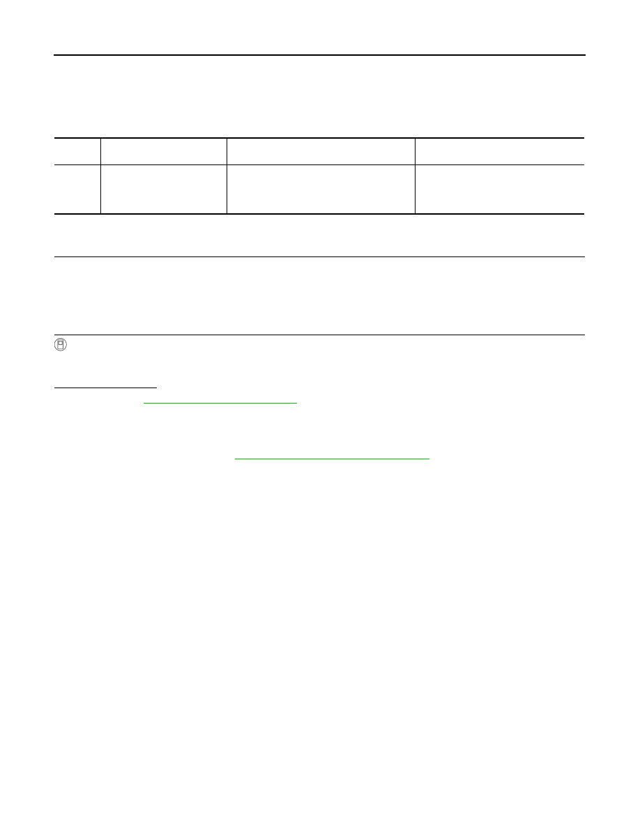
DTC
CONSULT screen terms
(Trouble diagnosis content)
DTC detection condition
Possible causes
U0102
LOST COMM (TRANSFER)
(Lost Communication With
Transfer Case Control Mod-
ule)
When the ignition switch is ON, TCM is unable
to receive the CAN communications signal
from 4WD control unit continuously for 2 sec-
onds or more.
• 4WD control unit
• Harness or connector
(CAN communication line is open or
shorted)