Qashqai J11. Transaxle & Transmission - part 11


  Index      Nissan     Qashqai J11. Transaxle & Transmission. Service and Repair Manual


Search            copyright infringement  


Content      ..     9      10      11      12     ..


Qashqai J11. Transaxle & Transmission - part 11


TM-162

< UNIT DISASSEMBLY AND ASSEMBLY >

[6MT: RS6F52A]

TRANSAXLE ASSEMBLY

4WD : Assembly

INFOID:0000000010288517
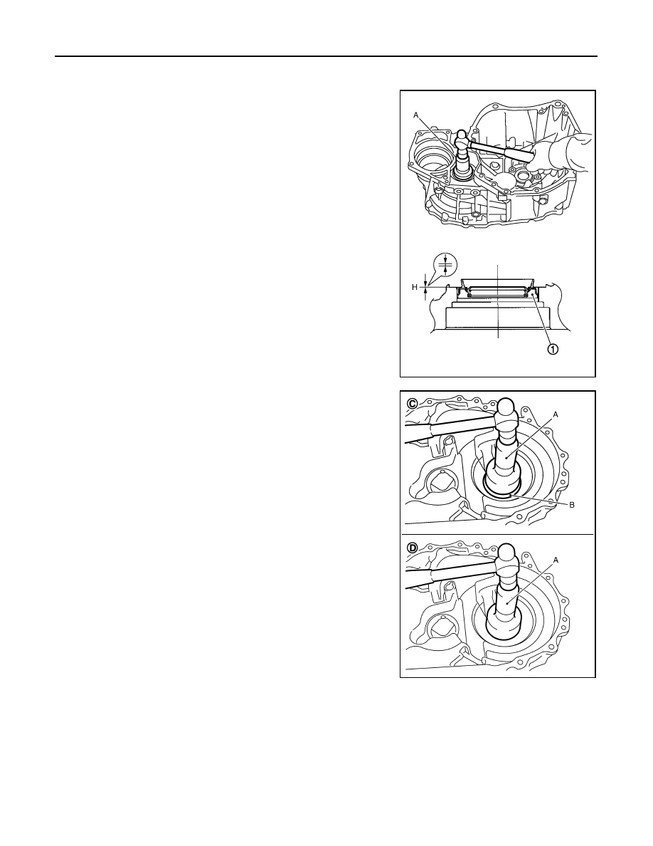
1.

Install differential side oil seal (1) to clutch housing using the drift
(A) [SST: ST33400001].

CAUTION:

• Never reuse differential side oil seal.
• When installing, never incline differential side oil seal.
• Never damage clutch housing.

2.

Install differential side bearing outer race (clutch housing side) to
clutch housing using the drifts.

CAUTION:

• Never reuse differential side bearing and differential side

bearing outer race.

• Replace differential side bearing and differential side

bearing outer race as a set.

Dimension “H”

: -0.5 - 0.5 mm (-0.020 - 0.020 in)

JPDIC0077ZZ

A

: Drift [SST: ST30720000]

B

: Drift [SST: KV40105320]

C

:  M9R

D

:  MR2ODE

JPDIC0132ZZ

TRANSAXLE ASSEMBLY

TM-163

< UNIT DISASSEMBLY AND ASSEMBLY >

[6MT: RS6F52A]

C

E

F

G

H

I

J

K

L

M

A

B

TM

N

O

P

3.

Install final drive assembly into clutch housing.

4.

Select differential side bearing adjusting shim. Refer to 

TM-173,

"4WD : Adjustment"

.

CAUTION:

Never select differential side bearing adjusting shim with
output gear assembly installed on clutch housing.

5.

Remove final drive assembly.

6.

Turn clutch housing upside down as shown in the figure. And
then install output gear assembly (1) into clutch housing.

CAUTION:

• Gently install it, aligning the clutch housing hole with the

center of output gear assembly.

• Install output gear assembly, straightening it with a mag-

net.

• Never damage clutch housing and output gear assembly.

7.

Install snap ring (1) onto clutch housing and make sure that end
play (gap between snap ring and groove) of output gear assem-
bly (2) satisfies the standard value.

CAUTION:

• Only one snap ring can be selected.
• Never reuse snap ring.
• Never damage clutch housing.

8.

Install input shaft oil seal (1) to clutch housing using the drift (A)
[SST: ST35321000].

CAUTION:

• Never reuse input shaft oil seal.
• When installing, never incline input shaft oil seal.
• Never damage clutch housing.

SCIA0888E

JPDIC0074ZZ

End play standard value 
“L”

: Refer to 

TM-207, 

"End Play"

.

JPDIC0043ZZ

Dimension “H”

: 1.1 - 2.1 mm (0.043 - 0.083 in)

PCIB1814E

TM-164

< UNIT DISASSEMBLY AND ASSEMBLY >

[6MT: RS6F52A]

TRANSAXLE ASSEMBLY

9.

Install oil channel (1) on mainshaft side.

CAUTION:

When installing oil channel, fit the rib (A) of oil channel into
the processed area of the spot facing (B).

10. Install mainshaft front bearing to clutch housing using the drift.

CAUTION:

Be careful with the orientation of mainshaft front bearing.

11. Install mainshaft bearing retainer (1) to clutch housing and

tighten mounting bolt to the specified torque.

CAUTION:

Install with punched surface facing up.

12. Install magnet to clutch housing.

13. Install final drive assembly into clutch housing.

CAUTION:

Engage reduction gear teeth in output gear teeth.

PCIB1921E

SCIA0401E

2

: Mainshaft front bearing

3

: Oil channel

PCIB1938E

PCIB1859E

SCIA0888E

TRANSAXLE ASSEMBLY

TM-165

< UNIT DISASSEMBLY AND ASSEMBLY >

[6MT: RS6F52A]

C

E

F

G

H

I

J

K

L

M

A

B

TM

N

O

P

14. Install input shaft assembly, mainshaft assembly, and reverse

idler gear assembly into clutch housing.

CAUTION:

• Wrap a tape, etc. to the spline of input shaft so as not to

damage the input shaft oil seal.

• Be careful with the orientation of reverse idler shaft.

15. Install striking rod assembly (1) into clutch housing.

CAUTION:

Check that return spring is securely seated in the groove on
return pin.

16. Install 1st-2nd shift fork (1) and 1st-2nd fork rod (2) and then

install retaining pin to 1st-2nd shift fork.

CAUTION:

• Never reuse retaining pin.
• Be careful with the orientation of 1st-2nd shift fork and

1st-2nd fork rod.

• Assemble retaining pin from the direction shown by the

arrow in the figure until it becomes flush with the end sur-
face of 1st-2nd shift fork.

SCIA0964E

PCIB1857E

PCIB1866E

PCIB1856E

TM-166

< UNIT DISASSEMBLY AND ASSEMBLY >

[6MT: RS6F52A]

TRANSAXLE ASSEMBLY

17. Install 3rd-4th shift fork (1) to 3rd-4th coupling sleeve.

CAUTION:

Be careful with the orientation of 3rd-4th shift fork.

18. Install 5th-6th shift fork (1) and 5th-6th fork rod (2) and then

install retaining pin to 5th-6th shift fork.

CAUTION:

• Never reuse retaining pin.
• Be careful with the orientation of 5th-6th shift fork and

5th-6th fork rod.

• Assemble retaining pin from the direction shown by the

arrow in the figure until it becomes flush with the end sur-
face of 5th-6th shift fork.

19. Install 3rd-4th fork rod (2) and then install retaining pin to 3rd-4th

shift fork (1).

CAUTION:

• Never reuse retaining pin.
• Be careful with the orientation of 3rd-4th fork rod.
• Assemble retaining pin from the direction shown by the

arrow in the figure until it becomes flush with the end sur-
face of 3rd-4th shift fork.

20. Install reverse shift fork (1) and reverse fork rod (2).

CAUTION:

Be careful with the orientation of reverse shift fork and
reverse fork rod.

21. Rotate striking lever of striking rod assembly as shown in the fig-

ure. Then rotate reverse fork rod to a position where bracket of
reverse fork rod does not interfere with striking lever of striking
rod assembly.

PCIB1855E

PCIB1852E

PCIB1853E

PCIB1875E

PCIB1851E

TRANSAXLE ASSEMBLY

TM-167

< UNIT DISASSEMBLY AND ASSEMBLY >

[6MT: RS6F52A]

C

E

F

G

H

I

J

K

L

M

A

B

TM

N

O

P

22. Install retaining pin to reverse shift fork (1).

CAUTION:

• Never reuse retaining pin.
• Assemble retaining pin from the direction shown by the

arrow in the figure until it becomes flush with the end sur-
face of reverse shift fork.

23. Install selected differential side bearing adjusting shim and differential side bearing outer race (transaxle

case side).
• For selection of adjusting shim, refer to 

TM-173, "4WD : Adjustment"

.

24. Install selected reverse idler gear adjusting shim onto reverse idler gear assembly.

• For selection of adjusting shim, refer to 

TM-173, "4WD : Adjustment"

.

25. Install selected input shaft rear bearing adjusting shim onto input shaft.

• For selection of adjusting shim, refer to 

TM-173, "4WD : Adjustment"

.

26. Install selected striking rod adjusting shim and striking rod shim onto striking rod assembly.

• For selection of adjusting shim, refer to 

TM-173, "4WD : Adjustment"

.

27. Install shifter lever oil seal (1) and striking rod oil seal (2) to tran-

saxle case using the drift [Commercial service tool].

CAUTION:

• Never reuse shifter lever oil seal and striking rod oil seal.
• When installing, never incline shifter lever oil seal and

striking rod oil seal.

• Never damage transaxle case.

28. Install differential side oil seal (1) to transaxle case using the drift

(A) [SST: ST30720000].

CAUTION:

• Never reuse differential side oil seal.
• When installing, never incline differential side oil seal.
• Never damage transaxle case.

2

: Reverse fork rod

PCIB1850E

Dimension “H”

: 0 - 1.0 mm (0 - 0.039 in)

PCIB1818E

Dimension “H”

: -0.5 - 0.5 mm (-0.020 - 0.020 in)

PCIB1878E

TM-168

< UNIT DISASSEMBLY AND ASSEMBLY >

[6MT: RS6F52A]

TRANSAXLE ASSEMBLY

29. Install shifter lever B (1) and shifter lever A (2) to transaxle case.

CAUTION:

Be careful with the orientation of shifter lever B and shifter
lever A.

30. Install retaining pin to shifter lever A.

CAUTION:

• Never reuse retaining pin.
• Assemble retaining pin from the direction shown by the

arrow in the figure until it becomes flush with the end sur-
face of shifter lever A.

31. Install transaxle case following the procedures below.

a.

Install selected mainshaft rear bearing adjusting shim into transaxle case.
• For selection of adjusting shim, refer to 

TM-173, "4WD : Adjustment"

.

b.

Install oil gutter A (1) and oil gutter B (2) to transaxle case.

CAUTION:

Insert the tab (A) of oil gutter A and oil gutter B into tran-
saxle case.

c.

Temporarily install snap ring of mainshaft rear bearing into tran-
saxle case.

CAUTION:

Never reuse snap ring.

PCIB1843E

PCIB1844E

PCIB1841E

PCIB1842E

TRANSAXLE ASSEMBLY

TM-169

< UNIT DISASSEMBLY AND ASSEMBLY >

[6MT: RS6F52A]

C

E

F

G

H

I

J

K

L

M

A

B

TM

N

O

P

d.

Apply recommended sealant to mating surface of clutch housing
as shown in the figure.
• Use Genuine Liquid Gasket, Three Bond 1215 or an equiv-

alent.

CAUTION:

• Remove old sealant adhering to the mounting surfaces.

Also remove any moisture, oil, or foreign material adher-
ing to both mounting surfaces.

• Apply sealant so as not to break the bead.
• The width of sealant bead is 1 - 2 mm (0.04 - 0.08 in).
• The height of sealant bead is 0.4 - 1 mm (0.016 - 0.04 in).
• The overlap length of both ends of sealant bead is 3 - 5

mm (0.12 - 0.20 in).

e.

With shifter lever A (1) held in the position shown in the figure,
temporarily assemble transaxle case to clutch housing.

CAUTION:

Never damage striking rod oil seal.
NOTE:
Make sure to hold shifter lever A in the position shown in the fig-
ure. Otherwise transaxle case cannot be installed to clutch
housing.

f.

While rotating shifter lever A (1) in the direction of the arrow in
the figure, assemble transaxle case to clutch housing.

g.

Accessing from the bore plug hole, expand snap ring at main-
shaft rear bearing so that the ring catches the periphery of main-
shaft rear bearing.

h.

Temporarily tighten transaxle case mounting bolts.

PCIB1807E

JPDIC0140ZZ

2

: Shifter lever B

JPDIC0141ZZ

PCIB1840E

TM-170

< UNIT DISASSEMBLY AND ASSEMBLY >

[6MT: RS6F52A]

TRANSAXLE ASSEMBLY

i.

Shift the shifter lever A (1) to 2nd gear position.
NOTE:
• The 2nd gear position is attained when shifter lever A is in the

position shown in the figure.

• When transaxle is shifted to the 2nd gear position, mainshaft

assembly is lifted.

j.

Seat snap ring in the groove on mainshaft rear bearing. If snap
ring is not seated in the groove on mainshaft rear bearing,
remove transaxle case and repeat the procedure from step d.

k.

Tighten transaxle case mounting bolts to the specified torque.

l.

Shift the shifter lever A (1) to neutral position.
NOTE:
The neutral position is attained when shifter lever A is in the
position shown in the figure.

PCIB1809E

SCIA0893E

PCIB1838E

PCIB1930E

TRANSAXLE ASSEMBLY

TM-171

< UNIT DISASSEMBLY AND ASSEMBLY >

[6MT: RS6F52A]

C

E

F

G

H

I

J

K

L

M

A

B

TM

N

O

P

32. Install bore plug to transaxle case using the drift.

CAUTION:

Never reuse bore plug.

33. Install selector lever to transaxle case and then install retaining

pin to selector lever.

CAUTION:

• Never reuse retaining pin.
• Assemble retaining pin from the direction shown by the

arrow in the figure until it becomes flush with the end sur-
face of selector lever.

34. Install guide bolt following the procedures below.

a.

Shift the shifter lever A and selector lever to neutral position.

b.

Visually confirm from the guide bolt mounting hole (C) that the
lever is securely set to neutral position. If it is not in the neutral
position, repeat the procedure from step a.

CAUTION:

The guide groove (D) of striking rod assembly will be dam-
aged when assembling guide bolt with the lever is in except
neutral position.

c.

Check continuity between terminals of park/neutral position
(PNP) switch to confirm it in the neutral position. If it is not in the
neutral position, remove park/neutral position (PNP) switch and
repeat the procedure from step a. Refer to 

TM-131, "Component

Inspection"

.

SCIA0894E

PCIB1837E

1

: Guide bolt

A

: Neutral position

B

: Except neutral position

PCIB1890E

TM-172

< UNIT DISASSEMBLY AND ASSEMBLY >

[6MT: RS6F52A]

TRANSAXLE ASSEMBLY

d.

Install guide bolt to transaxle case and then tighten guide bolt to
the specified torque.

CAUTION:

Never reuse guide bolt.

35. Apply recommended sealant to threads of park/neutral position

(PNP) switch (1). Then install it to transaxle case and tighten to
the specified torque.
• Use Genuine Liquid Gasket, Three Bond 1215 or an equiv-

alent.

CAUTION:

Remove old sealant and oil adhering to threads.

36. Install plunger to transaxle case.

37. Apply recommended sealant to threads of back-up lamp switch

(2). Then install it to transaxle case and tighten to the specified
torque.
• Use Genuine Liquid Gasket, Three Bond 1215 or an equiv-

alent.

CAUTION:

Remove old sealant and oil adhering to threads.

38. Install air breather tube (3) to transaxle case.

CAUTION:

• Never reuse air breather tube.
• Assemble air breather tube until its collar element contacts with transaxle case.

39. Install gasket onto plug and then install them into transaxle

case. Tighten plug to the specified torque.

CAUTION:

Never reuse gasket.

40. Install gasket onto drain plug and then install them into clutch

housing. Tighten drain plug to the specified torque.

CAUTION:

Never reuse gasket.

PCIB1836E

PCIB1835E

PCIB1865E

JPDIC0073ZZ

TRANSAXLE ASSEMBLY

TM-173

< UNIT DISASSEMBLY AND ASSEMBLY >

[6MT: RS6F52A]

C

E

F

G

H

I

J

K

L

M

A

B

TM

N

O

P

41. Install gasket onto filler plug and then install them into transaxle

case. Tighten filler plug to the specified torque.

CAUTION:

• Never reuse gasket.
• After gear oil is filled, tighten filler plug to specified

torque.

4WD : Adjustment

INFOID:0000000010288518

DIFFERENTIAL SIDE BEARING PRELOAD

• When adjusting differential side bearing preload, select adjusting

shim for differential side bearing. To select adjusting shim, mea-
sure clearance “L” between transaxle case and differential side
bearing outer race.

CAUTION:

Up to 2 adjusting shims can be selected.

• Calculate dimension “L” (thickness of adjusting shim) using the fol-

lowing procedure to satisfy specification of preload for differential
side bearing.

1.

Using a depth micrometer and straightedge, measure dimension
“L

1

” between transaxle case end face and mounting face of

adjusting shim.

CAUTION:

“L

1

”: Measure at 4 point by approximately 90 degrees and

use the average value.

2.

Install differential side bearing outer race onto differential side
bearing on final gear side. Holding lightly differential side bear-
ing outer race horizontally by hand, rotate final gear five times or
more (for smooth movement of bearing roller).

3.

Using a depth micrometer and straightedge as shown in the fig-
ure, measure dimension “L

2

” between differential side bearing

outer race and clutch housing end face.

CAUTION:

“L

2

”: Measure at 4 point by approximately 90 degrees and

use the average value.

JPDIC0047ZZ

Preload

: Refer to 

TM-209, "Differential Side Bearing 

Preload"

.

Dimension “L” = (L

1

 - L

2

) + Preload

L

: Thickness of adjusting shim

L

1

: Distance between transaxle case end face 
and mounting face of adjusting shim

L

2

: Distance between differential side bearing 
outer race and clutch housing end face

PCIB0795E

SCIA1078E

SCIA1079E

TM-174

< UNIT DISASSEMBLY AND ASSEMBLY >

[6MT: RS6F52A]

TRANSAXLE ASSEMBLY

4.

Install selected differential side bearing adjusting shim and then
install differential side bearing outer race (transaxle case side)
using the drift.

CAUTION:

Replace differential side bearing and differential side bear-
ing outer race as a set.

REVERSE IDLER GEAR END PLAY

• When adjusting reverse idler gear end play, select adjusting shim

for reverse idler gear. To select adjusting shim (1), measure clear-
ance between transaxle case (2) and reverse idler gear (rear) (3).

CAUTION:

Only 1 adjusting shim can be selected.

• Calculate dimension “Q” (thickness of adjusting shim) using the fol-

lowing procedure to satisfy specification of end play for reverse
idler gear.

1.

Using a depth micrometer and straightedge, measure dimension
“Q

1

” between transaxle case end face and mounting face of

adjusting shim.

2.

Using a depth micrometer and straightedge as shown in the fig-
ure, measure dimension “Q

2

” between clutch housing (1) end

face and end face of reverse idler gear (rear) (2).

CAUTION:

“Q

2

”: Measure at 4 point by approximately 90 degrees and

use the average value.

3.

Install selected reverse idler gear adjusting shim onto reverse
idler gear (rear).

INPUT SHAFT END PLAY

SCIA0898E

End play

: Refer to 

TM-207, "End Play"

.

Dimension “Q” = (Q

1

 - Q

2

) - End play

Q

: Thickness of adjusting shim

Q

1

: Distance between transaxle case end face 
and mounting face of adjusting shim

Q

2

: Distance between clutch housing end face 
and end face of reverse idler gear (rear)

PCIB1925E

SCIA1003E

PCIB1879E

TRANSAXLE ASSEMBLY

TM-175

< UNIT DISASSEMBLY AND ASSEMBLY >

[6MT: RS6F52A]

C

E

F

G

H

I

J

K

L

M

A

B

TM

N

O

P

• When adjusting input shaft end play, select adjusting shim for input

shaft rear bearing. To select adjusting shim, measure clearance
between transaxle case and input shaft rear bearing.

CAUTION:

Only 1 adjusting shim can be selected.

• Calculate dimension “O” (thickness of adjusting shim) using the fol-

lowing procedure to satisfy specification of end play for input shaft
rear bearing.

1.

Using a depth micrometer and straightedge, measure dimension
“O

1

” between transaxle case end face and mounting face of

adjusting shim.

CAUTION:

“O

1

”: Measure at 4 point by approximately 90 degrees and

use the average value.

2.

Using a depth micrometer and straightedge as shown in the fig-
ure, measure dimension “O

2

” between clutch housing end face

and end face of input shaft rear bearing.

CAUTION:

“O

2

”: Measure at 4 point by approximately 90 degrees and

use the average value.

3.

Install selected input shaft rear bearing adjusting shim onto input
shaft.

STRIKING ROD END PLAY

• When adjusting striking rod end play, select adjusting shim (1) for

striking rod (2). To select adjusting shim, measure clearance
between transaxle case (3) and striking rod shim (4).

CAUTION:

Only 1 adjusting shim can be selected.

• Calculate dimension “R” (thickness of adjusting shim) using the fol-

lowing procedure to satisfy specification of end play for striking
rod.

End play

Refer to 

TM-207, "End Play"

.

Dimension “O” = (O

1

 - O

2

) - End play

O

: Thickness of adjusting shim

O

1

: Distance between transaxle case end face 
and mounting face of adjusting shim

O

2

: Distance between clutch housing end face 
and end face of input shaft rear bearing

SCIA1001E

SCIA1002E

PCIB0792E

End play

: Refer to 

TM-207, "End Play"

.

Dimension “R” = (R

1

 - R

2

) - End play

R

: Thickness of adjusting shim

PCIB1823E

TM-176

< UNIT DISASSEMBLY AND ASSEMBLY >

[6MT: RS6F52A]

TRANSAXLE ASSEMBLY

1.

Using a depth micrometer (A) and straightedge (B), measure
dimension “R

1

” between transaxle case (1) end face and mount-

ing face of adjusting shim.

CAUTION:

“R

1

”: Measure at 4 point by approximately 90 degrees and

use the average value.

2.

Using a depth micrometer (A) and straightedge (B) as shown in
the figure, measure dimension “R

2

” between clutch housing (1)

end face and end face of striking rod shim (2).

CAUTION:

• “R

2

”: Measure at 4 point by approximately 90 degrees and

use the average value.

• When measuring, be careful for the inclination of striking

rod assembly and striking rod shim.

3.

Install selected striking rod adjusting shim onto striking rod
assembly.

MAINSHAFT END PLAY

• When adjusting mainshaft end play, select adjusting shim (1) for

mainshaft rear bearing (2). To select adjusting shim, measure
clearance “M” between transaxle case (3) and dummy adjusting
shim (4) on mainshaft rear bearing.

CAUTION:

Only 1 adjusting shim can be selected.

• Calculate dimension “P” (thickness of adjusting shim) using the fol-

lowing procedure to satisfy specification of end play for mainshaft
rear bearing.

*: Refer to the latest parts information to use a dummy adjusting shim of which part number is the thinnest in thickness.

1.

Install transaxle case following the procedures below.

R

1

: Distance between transaxle case end face 
and mounting face of adjusting shim

R

2

: Distance between clutch housing end face 
and end face of striking rod shim

PCIB1824E

PCIB1825E

5

:  Snap  ring

6

:  Mainshaft

End play

: Refer to 

TM-207, "End Play"

.

Dimension “P” = (M + N) - End play

P

: Thickness of adjusting shim

M

: Distance between dummy adjusting shim on 
mainshaft rear bearing end face and transaxle 
case end face

N*

: Thickness of dummy adjusting shim

JPDIC0146ZZ

TRANSAXLE ASSEMBLY

TM-177

< UNIT DISASSEMBLY AND ASSEMBLY >

[6MT: RS6F52A]

C

E

F

G

H

I

J

K

L

M

A

B

TM

N

O

P

a.

Temporarily install snap ring of mainshaft rear bearing into tran-
saxle case.

CAUTION:

Never reuse snap ring.

b.

Install dummy adjusting shim (1) to mainshaft assembly.

c.

With shifter lever A (1) held in the position shown in the figure,
temporarily assemble transaxle case to clutch housing.

CAUTION:

Never damage striking rod oil seal.
NOTE:
Make sure to hold shifter lever A in the position shown in the fig-
ure. Otherwise transaxle case cannot be installed to clutch
housing.

d.

While rotating shifter lever A (1) in the direction of the arrow
shown in the figure, assemble transaxle case to clutch housing.

e.

Accessing from the bore plug hole, expand snap ring at main-
shaft rear bearing so that the ring catches the periphery of main-
shaft rear bearing.

f.

Temporarily tighten transaxle case mounting bolts.

PCIB1842E

PCIB1826E

JPDIC0140ZZ

2

: Shifter lever B

JPDIC0141ZZ

PCIB1840E


Content      ..     9      10      11      12     ..