Qashqai J11. Brake control system - part 4


  Index      Nissan     Qashqai J11. Brake control system. Service and Repair Manual


Search            copyright infringement  


Content      ..     2      3      4      5     ..


Qashqai J11. Brake control system - part 4


ABS ACTUATOR AND ELECTRIC UNIT (CONTROL UNIT)

BRC-49

< ECU DIAGNOSIS INFORMATION >

[WITH ESP]

C

D

E

G

H

I

J

K

L

M

A

B

BRC

N

O

P

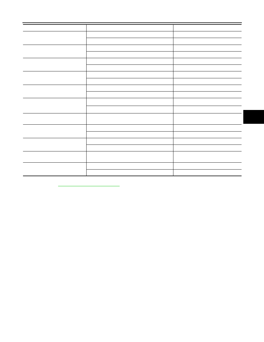
Note 1: Confirm tire pressure is standard value.
Note 2: Refer to 

BRC-13, "System Description"

 for ON/OFF conditions of each warning lamp and indicator

lamp.
Note 3: AWD models
Note 4: USS (Hill Start Assist)

Fail-Safe

INFOID:0000000010427932

VDC FUNCTION, TCS FUNCTION, BRAKE LIMITED SLIP DIFFERENTIAL FUNCTION, BRAKE AS-
SIST FUNCTION, hill start assist FUNCTION AND BRAKE FORCE DISTRIBUTION FUNCTION

VDC warning lamp in combination meter turn ON when a malfunction occurs in system [ABS actuator and
electric unit (control unit)]. The control is suspended for VDC function, TCS function, Brake limited slip differ-
ential (BLSD) function, Brake assist function, hill start assist function and Brake force distribution function. The
vehicle status becomes the same as models without VDC function, TCS function, Brake limited slip differential
(BLSD) function, Brake assist function, hill start assist function and Brake force distribution function. However,
ABS function and EBD function are operated normally.

ABS FUNCTION

ABS warning lamp and VDC warning lamp in combination meter turn ON when a malfunction occurs in system
[ABS actuator and electric unit (control unit)]. The control is suspended for VDC function, TCS function, ABS
function, Brake limited slip differential (BLSD) function, Brake assist function, hill start assist function and
Brake force distribution function. The vehicle status becomes the same as models without VDC function, TCS
function, ABS function, Brake limited slip differential (BLSD) function, Brake assist function, hill start assist
function and Brake force distribution function. However, EBD function is operated normally.
NOTE:
ABS self-diagnosis sound may be heard the same as in the normal condition, because self-diagnosis is per-
formed when ignition switch turns ON and when vehicle initially starts.

EBD FUNCTION

ABS warning lamp, brake warning lamp and VDC warning lamp in combination meter turn ON when a mal-
function occurs in system [ABS actuator and electric unit (control unit)]. The control is suspended for VDC

EBD FAIL SIG

In EBD fail-safe

On

EBD is normal

Off

ABS FAIL SIG

In ABS fail-safe

On

ABS is normal

Off

TCS FAIL SIG

In TCS fail-safe

On

TCS is normal

Off

VDC FAIL SIG

In VDC fail-safe

On

VDC is normal

Off

CRANKING SIG

At cranking

On

Other than at cranking

Off

EBD WARN LAMP

When brake warning lamp is ON

(Note 2)

On

When brake warning lamp is OFF

(Note 2)

Off

GEAR

Driving

1 – 7
Depending on shift status

N POSI SIG

When selector lever is in the N position

On

When selector lever is in the other position than N

Off

R POSI SIG

When selector lever is in the R position

On

When selector lever is in the other position than R

Off

4WD MODE MON

(Note 3)

Always

AUTO, LOCK, 2WD (depending on 4WD 
control status)

USS SIG

(Note 4)

When hill start assist is active

On

When hill start assist is not active

Off

Monitor item

Condition

Reference values in normal operation

BRC-50

< ECU DIAGNOSIS INFORMATION >

[WITH ESP]

ABS ACTUATOR AND ELECTRIC UNIT (CONTROL UNIT)

function, TCS function, ABS function, EBD function, Brake limited slip differential (BLSD) function, Brake
assist function, hill start assist function and Brake force distribution function. The vehicle status becomes the
same as models without VDC function, TCS function, ABS function, EBD function, Brake limited slip differen-
tial (BLSD) function, Brake assist function, hill start assist function and Brake force distribution function.

DTC

Fail-safe condition

C1101

The following functions are suspended:
• VDC function
• TCS function
• ABS function
• EBD function (only when both 2 rear wheels are malfunctioning)
• Brake limited slip differential (BLSD) function
• Brake assist function
• hill start assist function
• Brake force distribution function
• Active trace control function (control of chassis control module)

C1102

C1103

C1104

C1105

C1106

C1107

C1108

C1109

The following functions are suspended:
• VDC function
• TCS function
• ABS function
• EBD function
• Brake limited slip differential (BLSD) function
• Brake assist function
• hill start assist function
• Brake force distribution function
• Active trace control function (control of chassis control module)

C1111

C1113

C1115

The following functions are suspended:
• VDC function
• TCS function
• ABS function
• Brake limited slip differential (BLSD) function
• Brake assist function
• hill start assist function
• Brake force distribution function
• Active trace control function (control of chassis control module)

C1120

The following functions are suspended:
• VDC function
• TCS function
• ABS function
• EBD function
• Brake limited slip differential (BLSD) function
• Brake assist function
• hill start assist function
• Brake force distribution function
• Active trace control function (control of chassis control module)

C1121

C1122

C1123

C1124

C1125

C1126

C1127

C1130

The following functions are suspended:
• VDC function
• TCS function
• Brake limited slip differential (BLSD) function
• hill start assist function
• Brake force distribution function
• Active trace control function (control of chassis control module)

C1138

ABS ACTUATOR AND ELECTRIC UNIT (CONTROL UNIT)

BRC-51

< ECU DIAGNOSIS INFORMATION >

[WITH ESP]

C

D

E

G

H

I

J

K

L

M

A

B

BRC

N

O

P

C1140

The following functions are suspended:
• VDC function
• TCS function
• ABS function
• EBD function
• Brake limited slip differential (BLSD) function
• Brake assist function
• hill start assist function
• Brake force distribution function
• Active trace control function (control of chassis control module)

C1142

The following functions are suspended:
• VDC function
• TCS function
• Brake limited slip differential (BLSD) function
• Brake assist function
• hill start assist function
• Brake force distribution function
• Active trace control function (control of chassis control module)

C1143

The following functions are suspended:
• VDC function
• TCS function
• Brake limited slip differential (BLSD) function
• hill start assist function
• Brake force distribution function
• Active trace control function (control of chassis control module)

C1144

C1145

The following functions are suspended:
• VDC function
• TCS function
• ABS function
• Brake limited slip differential (BLSD) function
• Brake assist function
• hill start assist function
• Brake force distribution function
• Active trace control function (control of chassis control module)

C1146

C1155

The following functions are suspended:
• VDC function
• TCS function
• Brake limited slip differential (BLSD) function
• Brake assist function
• hill start assist function
• Brake force distribution function
• Active trace control function (control of chassis control module)

C1160

The following functions are suspended:
• VDC function
• TCS function
• ABS function
• Brake limited slip differential (BLSD) function
• Brake assist function
• hill start assist function
• Brake force distribution function
• Active trace control function (control of chassis control module)

C1164

The following functions are suspended:
• VDC function
• TCS function
• ABS function
• EBD function
• Brake limited slip differential (BLSD) function
• Brake assist function
• hill start assist function
• Brake force distribution function
• Active trace control function (control of chassis control module)

C1165

DTC

Fail-safe condition

BRC-52

< ECU DIAGNOSIS INFORMATION >

[WITH ESP]

ABS ACTUATOR AND ELECTRIC UNIT (CONTROL UNIT)

DTC Inspection Priority Chart

INFOID:0000000010427933

When multiple DTCs are displayed simultaneously, check one by one depending on the following priority list.

C1170

The following functions are suspended:
• VDC function
• TCS function
• ABS function
• Brake limited slip differential (BLSD) function
• Brake assist function
• hill start assist function
• Brake force distribution function
• Active trace control function (control of chassis control module)

C1197

Electrical vacuum assistance of brake booster is suspended.

C1198

C1199

C119A

Electrical vacuum assistance of brake booster is suspended.

U1000
U1002
U1010

The following functions are suspended:
• VDC function
• TCS function
• Brake limited slip differential (BLSD) function
• hill start assist function
• Brake force distribution function
• Active trace control function (control of chassis control module)

DTC

Fail-safe condition

Priority

Detected item (DTC)

1

• U1000 CAN COMM CIRCUIT

2

• C1170 VARIANT CODING

3

• C1130 ENGINE SIGNAL 1
• C1144 ST ANG SEN SIGNAL
• C1138 4WAS CIRCUIT

4

• C1109 BATTERY VOLTAGE [ABNOMAL]
• C1111 PUMP MOTOR
• C1140  ACTUATOR  RLY

ABS ACTUATOR AND ELECTRIC UNIT (CONTROL UNIT)

BRC-53

< ECU DIAGNOSIS INFORMATION >

[WITH ESP]

C

D

E

G

H

I

J

K

L

M

A

B

BRC

N

O

P

DTC Index

INFOID:0000000010427934

5

• C1101 RR RH SENSOR-1
• C1102 RR LH SENSOR-1
• C1103 FR RH SENSOR-1
• C1104 FR LH SENSOR-1
• C1105 RR RH SENSOR-2
• C1106 RR LH SENSOR-2
• C1107 FR RH SENSOR-2
• C1108 FR LH SENSOR-2
• C1113 G SENSOR
• C1120 FR LH IN ABS SOL
• C1121 FR LH OUT ABS SOL
• C1122 FR RH IN ABS SOL
• C1123 FR RH OUT ABS SOL
• C1124 RR LH IN ABS SOL
• C1125 RR LH OUT ABS SOL
• C1126 RR RH IN ABS SOL
• C1127 RR RH OUT ABS SOL
• C1142 PRESS SEN CIRCUIT
• C1143 ST ANG SEN CIRCUIT
• C1145 YAW RATE SENSOR
• C1146 SIDE G SEN CIRCUIT
• C1160 DECEL G SEN SET
• C1164  CV  1
• C1165  CV  2
• C1197 VACUUM SENSOR
• C1198 VACUUM SEN CIR
• C1199 BRAKE BOOSTER
• C119A VACUUM SEN VOLT

6

• C1155 BR FLUID LEVEL LOW

Priority

Detected item (DTC)

DTC

Display Item

VDC warning 

lamp

ABS warning 

lamp

Brake warning 

lamp

Refer to

C10D7

PARKING BRAKE SYSTEM

ON

ON

ON

BRC-70, "DTC Logic"

C1101

RR RH SENSOR-1

ON

ON

OFF

BRC-71, "DTC Logic"

C1102

RR LH SENSOR-1

ON

ON

OFF

C1103

FR RH SENSOR-1

ON

ON

OFF

C1104

FR LH SENSOR-1

ON

ON

OFF

C1105

RR RH SENSOR-2

ON

ON

OFF

BRC-76, "DTC Logic"

C1106

RR LH SENSOR-2

ON

ON

OFF

C1107

FR RH SENSOR-2

ON

ON

OFF

C1108

FR LH SENSOR-2

ON

ON

OFF

C1109

BATTERY VOLTAGE [ABNOMAL]

ON

ON

ON

BRC-78, "DTC Logic"

C1109

BATTERY VOLTAGE [ABNOMAL]

ON

ON

ON

BRC-78, "DTC Logic"

C1110

CONTROLLER FAILURE

ON

ON

ON

BRC-80, "DTC Logic"

C1113

G SENSOR

ON

ON

OFF

BRC-84, "DTC Logic"

C1115

ABS SENSOR [ABNORMAL SIGNAL]

ON

ON

OFF

BRC-85, "DTC Logic"

C1116

STOP LAMP SW

ON

ON

OFF

BRC-87, "DTC Logic"

C1120

FR LH IN ABS SOL

ON

ON

ON

BRC-90, "DTC Logic"

C1121

FR LH OUT ABS SOL

ON

ON

ON

BRC-92, "DTC Logic"

C1122

FR RH IN ABS SOL

ON

ON

ON

BRC-90, "DTC Logic"

C1123

FR RH OUT ABS SOL

ON

ON

ON

BRC-92, "DTC Logic"

BRC-54

< ECU DIAGNOSIS INFORMATION >

[WITH ESP]

ABS ACTUATOR AND ELECTRIC UNIT (CONTROL UNIT)

C1124

RR LH IN ABS SOL

ON

ON

ON

BRC-90, "DTC Logic"

C1125

RR LH OUT ABS SOL

ON

ON

ON

BRC-92, "DTC Logic"

C1126

RR RH IN ABS SOL

ON

ON

ON

BRC-90, "DTC Logic"

C1127

RR RH OUT ABS SOL

ON

ON

ON

BRC-92, "DTC Logic"

C1130

ENGINE SIGNAL 1

ON

OFF

OFF

BRC-94, "DTC Logic"

C1140

ACTUATOR RLY

ON

ON

ON

BRC-95, "DTC Logic"

C1142

PRESS SEN CIRCUIT

ON

OFF

OFF

BRC-97, "DTC Logic"

C1143

ST ANG SEN CIRCUIT

ON

OFF

OFF

BRC-99, "DTC Logic"

C1144

ST ANG SEN SIGNAL

ON

OFF

OFF

BRC-101, "DTC Logic"

C1145

YAW RATE SENSOR

ON

ON

OFF

BRC-84, "DTC Logic"

C1146

SIDE G SEN CIRCUIT

ON

ON

OFF

C1153

EMERGENCY BRAKE

ON

ON

ON

BRC-80, "DTC Logic"

C1154

PNP POSI SIG

ON

ON

ON

BRC-102, "DTC Logic"

C1155

BR FLUID LEVEL LOW

ON

OFF

OFF

BRC-103, "DTC Logic"

C1160

DECEL G SEN SET

ON

ON

OFF

BRC-105, "DTC Logic"

C1164

CV 1

ON

ON

ON

BRC-106, "DTC Logic"

C1165

CV 2

ON

ON

ON

C1166

SV  1

ON

ON

ON

BRC-108, "DTC Logic"

C1167

SV  2

ON

ON

ON

C1170

VARIANT CODING

ON

ON

OFF

BRC-110, "DTC Logic"

C1197

VACUUM SENSOR

OFF

OFF

ON

BRC-111, "DTC Logic"

C1198

VACUUM SEN CIR

OFF

OFF

ON

BRC-113, "DTC Logic"

C1199

BRAKE BOOSTER

OFF

OFF

ON

BRC-115, "DTC Logic"

C1B60

EXTERNAL CONTROL MODULE

ON

ON

ON

BRC-119, "DTC Logic"

C119A

VACUUM SEN VOLT

OFF

OFF

ON

BRC-117, "DTC Logic"

U1000

CAN COMM CIRCUIT

ON

OFF

OFF

BRC-120, "DTC Logic"

U1002

CAN COMM CIRCUIT

ON

OFF

OFF

U1010

CONTROL UNIT CAN

ON

OFF

OFF

BRC-121, "DTC Logic"

DTC

Display Item

VDC warning 

lamp

ABS warning 

lamp

Brake warning 

lamp

Refer to

BRAKE CONTROL SYSTEM

BRC-55

< WIRING DIAGRAM >

[WITH ESP]

C

D

E

G

H

I

J

K

L

M

A

B

BRC

N

O

P

WIRING DIAGRAM

BRAKE CONTROL SYSTEM

Wiring Diagram

INFOID:0000000010329807

JRFWC1332GB

BRC-56

< WIRING DIAGRAM >

[WITH ESP]

BRAKE CONTROL SYSTEM

JRFWC1349GB

BRAKE CONTROL SYSTEM

BRC-57

< WIRING DIAGRAM >

[WITH ESP]

C

D

E

G

H

I

J

K

L

M

A

B

BRC

N

O

P

JRFWC1350GB

BRC-58

< WIRING DIAGRAM >

[WITH ESP]

BRAKE CONTROL SYSTEM

JRFWC1351GB

BRAKE CONTROL SYSTEM

BRC-59

< WIRING DIAGRAM >

[WITH ESP]

C

D

E

G

H

I

J

K

L

M

A

B

BRC

N

O

P

JRFWC1352GB

BRC-60

< BASIC INSPECTION >

[WITH ESP]

DIAGNOSIS AND REPAIR WORK FLOW

BASIC INSPECTION

DIAGNOSIS AND REPAIR WORK FLOW

Work Flow

INFOID:0000000010428737

DETAILED FLOW

1.

INTERVIEW FROM THE CUSTOMER

Clarify customer complaints before inspection. First of all, perform an interview utilizing 

BRC-61, "Diagnostic

Work Sheet"

 and reproduce the symptom as well as fully understand it. Ask customer about his/her complaints

carefully. Check symptoms by driving vehicle with customer, if necessary.

CAUTION:

Customers are not professional. Never guess easily like “maybe the customer means that...,” or “
maybe the customer mentions this symptom”.

>> GO TO 2.

2.

CHECK SYMPTOM

Reproduce the symptom that is indicated by the customer, based on the information from the customer
obtained by interview. Also check that the symptom is not caused by fail-safe mode. Refer to 

BRC-49, "Fail-

Safe"

.

CAUTION:

When the symptom is caused by normal operation, fully inspect each portion and obtain the under-
standing of customer that the symptom is not caused by a malfunction.

>> GO TO 3.

3.

PERFORM THE SELF-DIAGNOSIS

With CONSULT

1.

Turn the ignition switch OFF 

 ON.

CAUTION:

Be sure to wait of 10 seconds after turning ignition switch OFF or ON.

2.

Repeat step 1 two or more times.

3.

Perform self-diagnosis for “ABS”.

Is DTC detected?

YES

>> Record or print self-diagnosis results and freeze frame data (FFD). GO TO 4.

NO

>> GO TO 6.

4.

RECHECK THE SYMPTOM

With CONSULT

1.

Erase self-diagnostic results for “ABS”.

2.

Turn the ignition switch OFF 

 ON 

 OFF.

CAUTION:

Be sure to wait of 10 seconds after turning ignition switch OFF or ON.

3.

Perform DTC confirmation procedures for the error-detected system.
NOTE:
If some DTCs are detected at the some time, determine the order for performing the diagnosis based on

BRC-52, "DTC Inspection Priority Chart"

.

Is any DTC detected?

YES

>> GO TO 5.

NO

>> Check harness and connectors based on the information obtained by interview. Refer to 

GI-41,

"Intermittent Incident"

.

5.

REPAIR OR REPLACE ERROR-DETECTED PART

1.

Repair or replace error-detected parts.

2.

Reconnect part or connector after repairing or replacing.

3.

When DTC is detected, erase self-diagnostic result for “ABS”.

DIAGNOSIS AND REPAIR WORK FLOW

BRC-61

< BASIC INSPECTION >

[WITH ESP]

C

D

E

G

H

I

J

K

L

M

A

B

BRC

N

O

P

CAUTION:

• Turn the ignition switch OFF 

 ON 

 OFF after erase self-diagnosis result.

• Be sure to wait of 10 seconds after turning ignition switch OFF or ON.

>> GO TO 7.

6.

IDENTIFY ERROR-DETECTED SYSTEM BY SYMPTOM DIAGNOSIS

Estimate error-detected system based on symptom diagnosis and perform inspection.

Can the error-detected system be identified?

YES

>> GO TO 7.

NO

>> Check harness and connectors based on the information obtained by interview. Refer to 

GI-41,

"Intermittent Incident"

.

7.

FINAL CHECK

With CONSULT

1.

Check the reference value for “ABS”.

2.

Recheck the symptom and check that the symptom is not reproduced on the same conditions.

Is the symptom reproduced? 

YES

>> GO TO 3.

NO

>> Inspection End.

Diagnostic Work Sheet

INFOID:0000000010428738

Description

• In general, customers have their own criteria for a problem. Therefore, it is important to understand the

symptom and status well enough by asking the customer about his/her concerns carefully. To systemize all
the information for the diagnosis, prepare the interview sheet referring to the interview points.

• In some cases, multiple conditions that appear simultaneously may cause a DTC to be detected.

INTERVIEW SHEET SAMPLE

Interview sheet

Customer 
name

MR/MS

Registration 
number

Initial year 
registration

Vehicle type

VIN

Storage date

Engine

Mileage

km (Mile)

Symptom

†

 Does not operate (                                                                                                  ) function

†

 Warning lamp for (                                                                                                 ) turns ON.

†

 Noise

†

 Vibration

†

 Other

(                                                                                                                                                 )

First occurrence

†

 Recently        

†

 Other (                                                                                                       )

Frequency of occurrence

†

 Always          

†

  Under a certain conditions of           

†

 Sometimes (              time(s)/day)

Climate con-
ditions

†

 Irrelevant

Weather

†

 Fine         

†

 Cloud           

†

 Rain           

†

Snow        

†

 Others (                                       )

Temperature

†

 Hot          

†

Warm           

†

 Cool           

†

 Cold           

†

 Temperature [Approx.             

°

C (

°

F)]

Relative humidity

†

 High                  

†

 Moderate                    

†

 Low

Road conditions

†

 Urban area             

†

 Suburb area                    

†

 Highway              

†

 Mountainous road (uphill or downhill)                

†

Rough road

Operating condition, etc.

†

Irrelevant

†

When engine starts          

†

 During idling

†

 During driving            

†

 During acceleration             

†

 At constant speed driving              

†

 During deceleration

†

 During cornering (right curve or left curve)

†

 When steering wheel is steered (to right or to left)

BRC-62

< BASIC INSPECTION >

[WITH ESP]

DIAGNOSIS AND REPAIR WORK FLOW

Other conditions

Memo

Interview sheet

Customer 
name

MR/MS

Registration 
number

Initial year 
registration

Vehicle type

VIN

Storage date

Engine

Mileage

km (Mile)

ADDITIONAL SERVICE WHEN REPLACING ABS ACTUATOR AND ELECTRIC 

UNIT (CONTROL UNIT)

BRC-63

< BASIC INSPECTION >

[WITH ESP]

C

D

E

G

H

I

J

K

L

M

A

B

BRC

N

O

P

ADDITIONAL SERVICE WHEN REPLACING ABS ACTUATOR AND ELEC-
TRIC UNIT (CONTROL UNIT)

Description

INFOID:0000000010428739

• When replaced the ABS actuator and electric unit (control unit), perform adjust the neutral position of steer-

ing angle sensor. Refer to 

BRC-66, "Work Procedure"

.

• When replaced the ABS actuator and electric unit (control unit), perform calibration of the decel G sensor.

Refer to 

BRC-66, "Work Procedure"

.

BRC-64

< BASIC INSPECTION >

[WITH ESP]

ADJUSTMENT OF STEERING ANGLE SENSOR NEUTRAL POSITION

ADJUSTMENT OF STEERING ANGLE SENSOR NEUTRAL POSITION

Description

INFOID:0000000010428740

Refer to the table below to determine if adjustment of steering angle sensor neutral position is required.

×

: Required –: Not required

Work Procedure

INFOID:0000000010428741

ADJUSTMENT OF STEERING ANGLE SENSOR NEUTRAL POSITION

CAUTION:

To adjust neutral position of steering angle sensor, make sure to use CONSULT.
(Adjustment cannot be done without CONSULT).

1.

ALIGN THE VEHICLE STATUS

Stop vehicle with front wheels in straight-ahead position.

>> GO TO 2.

2.

PERFORM THE NEUTRAL POSITION ADJUSTMENT FOR THE STEERING ANGLE SENSOR

1.

On the CONSULT screen, touch “WORK SUPPORT” and “ST ANG SENSOR ADJUSTMENT” in order.

2.

Touch “START”.

CAUTION:

Do not touch steering wheel while adjusting steering angle sensor.

3.

After approximately 10 seconds, touch “END”.
NOTE:
After approximately 60 seconds, it ends automatically.

4.

Turn ignition switch OFF, then turn it ON again.

CAUTION:

Be sure to perform above operation.

>> GO TO 3.

3.

CHECK DATA MONITOR

1.

Run vehicle with front wheels in straight-ahead position, then stop.

2.

Select “DATA MONITOR”. Then make sure “STR ANGLE SIG” is within 0

±

3.5

°

.

Is the steering angle within the specified range?

YES

>> GO TO 4.

NO

>> Perform the neutral position adjustment for the steering angle sensor again, GO TO 1.

4.

ERASE THE SELF-DIAGNOSIS MEMORY

Erase the self-diagnosis memory of the ABS actuator and electric unit (control unit) and ECM.
• ABS actuator and electric unit (control unit): Refer to 

BRC-42, "CONSULT Function"

.

Situation

Adjustment of steering angle sensor neutral position

Removing/Installing ABS actuator and electric unit (control unit)

Replacing ABS actuator and electric unit (control unit)

×

Removing/Installing steering angle sensor

×

Replacing steering angle sensor

×

Removing/Installing steering components

×

Replacing steering components

×

Removing/Installing suspension components

×

Replacing suspension components

×

Change tires to new ones

Tire rotation

Adjusting wheel alignment

×


Content      ..     2      3      4      5     ..