Mitsubishi Outlander PHEV (2019 year). Instruction - part 21


  Index      Mitsubishi     Mitsubishi Outlander PHEV - instruction 2019 year in english


Search            


Content   ..  19  20  21  22   ..


Mitsubishi Outlander PHEV (2019 year). Instruction - part 21


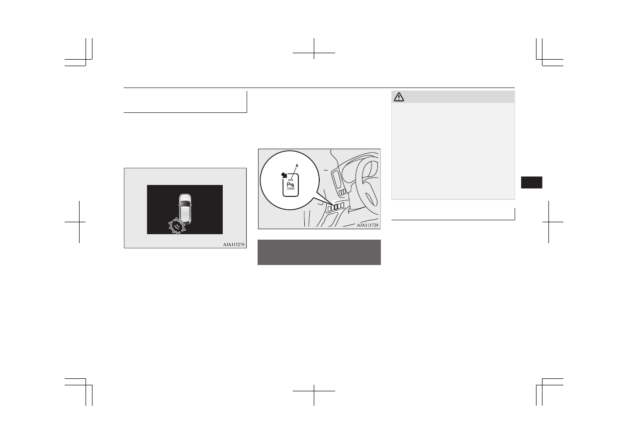
Reversing sensor system warn-

ing display

E00615901519

In case there is a malfunction in the reversing
sensor  system,  the  display  for  the  malfunc-
tioning  sensor  will  blink  and  the  warning
buzzer  will  sound  for  approximately  5  sec-
onds.

Example: Corner sensor (left) malfunctioning

Even after the buzzer and display has stopped
warning,  the  indication  lamp  (A)  on  “SO-
NAR” switch will continue blinking until the
system  reverts  to  the  normal  state.  Have  the
vehicle  inspected  at  a  MITSUBISHI
MOTORS Authorized Service Point.

Parking sensors (Front/
Rear)*

E00647700092

When  parking  in  a  garage  or  during  parallel
parking, these sensors alert the driver to any
objects  near  the  vehicle  and  their  distance,
through  a  buzzer  and  the  sensor  display  on
the  information  screen  in  the  multi-informa-
tion display.

CAUTION

l

The  parking  sensors  assist  you  in  determin-
ing  the  approximate  distance  between  the
vehicle and any objects. It has limitations in
terms  of  detectable  areas  and  objects,  and
may  not  properly  detect  some  objects.
Therefore, do not place excessive confidence
in the parking sensors, and operate the vehi-
cle as carefully as you would do with vehicle
not equipped with this system.

l

Make  sure  to  check  the  surroundings  with
your own eyes to ensure safety. Do not oper-
ate the vehicle by relying on the parking sen-
sors alone.

Obstacle detection areas

E00647800136

The  detection  areas  of  the  corner  and  back
sensors  are  limited  to  those  shown  in  the  il-
lustration.  Moreover,  the  sensors  are  unable
to  detect  low  or  thin  objects  or  objects  near
the front or rear bumper. Thus, make sure to
check the surroundings as you operate the ve-
hicle in a safe manner.

Parking sensors (Front/Rear)*

7-101

OGGE19E1

Starting and driving

7

Corner  and  back  sensor  loca-

tions

There are 8 sensors (A) in the front and rear
bumper.

Detection areas

Depending  on  whether  the  vehicle  is  equip-
ped  with  a  towing  bar,  you  can  change  the
parking  sensors  between  the  standard  mode
and  the  towing  bar  mode.  The  towing  bar
mode changes the system to exclude the area
in which the towing bar is mounted from the
detection areas.

Vehicles without a towing bar
The detection areas are within approximately
60 cm (A) from the front and corner sensors
and 125 cm (B) from the back sensors.

Vehicles with a towing bar
The detection areas are within approximately
60 cm (A) from the front and corner sensors
and  125  cm  (B)  from  the  back  sensors.  The
non-detection  areas  (C)  are  within  approxi-
mately 20 cm (D) from the bumper.

NOTE

l

The sensors do not detect objects located in
the  area  directly  below  or  near  the  bumper.
If  the  height  of  an  object  is  lower  than  the
mounted position of the sensors, the sensors
may  not  continue  detecting  it  even  if  they
detected it initially.

For information on how to change the detec-
tion areas, please refer to “Changing the de-
tection areas” on page 7-100.

Parking sensors (Front/Rear)*

7-102

OGGE19E1

Starting and driving

7

CAUTION

l

The parking sensors may not operate proper-
ly under the following conditions:

The  sensors  or  surroundings  have  been
wiped by hand.

The  stickers  or  accessories  have  been  at-
tached to the sensors or surroundings.

The  sensors  or  surroundings  are  covered
with ice, snow, or mud.

When  the  temperature  difference  is  too
large.

The sensors are frozen.

The system receives ultrasonic noise from
other sources (the horns of other vehicles,
motorcycle  engines,  brakes,  radios,  pour-
ing  rain,  splashing  water,  snow  traction
device (tyre chains), etc.).

The  sensors  are  extremely  hot  or  cold
(while the vehicle is parked for a long pe-
riod of time under a blazing sun or in cold
weather).

The vehicle tilts significantly.

The  vehicle  is  driven  on  a  rough  road
(with a bumpy, gravel, hilly, or grassy sur-
face).

The vehicle is too close to an obstacle.

Immediately  after  Plug-in  Hybrid  EV
System starting.

l

The parking sensors may not properly detect
the following objects:

Objects that are thin, such as wire nets or
ropes.

Objects that absorb sound waves, such as
snow.

Objects  that  are  shaped  with  a  sharp  an-
gle.

CAUTION

Objects  with  a  smooth  surface,  such  as
glass.

Objects that are low, such as kerbstones.

l

If  the  bumper  has  been  exposed  to  an  im-
pact,  the  sensors  may  fail  and  prevent  the
system  from  functioning  properly.  Have  the
vehicle  inspected  at  a  MITSUBISHI
MOTORS Authorized Service Point.

NOTE

l

When the sensor is received ultrasonic noise
from  outside,  the  sensor  of  the  correspond-
ing portion will blink at a constant frequen-
cy. When they are not received the noise and
return to normal operation.

To operate

E00648100149

To operate the system, the operation mode is
put in ON. When the parking sensors are op-
erated,  the  indication  lamp  (A)  will  turn  on.
To  stop  the  operation,  press  the  “SONAR”
switch and the indication lamp (A) goes off.

Parking sensors (Front/Rear)*

7-103

OGGE19E1

Starting and driving

7

Warning for obstacles

If  there  is  an  obstacle  in  the  vicinity  of  the
vehicle, a warning will be issued with the in-
formation screen in the multi information dis-
play and a warning buzzer.

1- Corner sensor
2- Front sensor
3- Back sensor

Front and corner sensor

Vehicle to obstacle

distance

Warning display/

sound cycle

Approx. 60 to 40 cm

Intermittent

Approx. 40 to 30 cm

Fast intermittent

Within approx.

30 cm

Continuous

Back  sensor  (vehicles  without  a  towing
bar)

Vehicle to obstacle

distance

Warning display/

sound cycle

Approx. 125 to

80 cm

Intermittent

Approx. 80 to 40 cm

Fast intermittent

Within approx.

40 cm

Continuous

Back sensor (vehicles with a towing bar)

Vehicle to obstacle

distance

Warning display/

sound cycle

Approx. 125 to

100 cm

Intermittent

Approx. 100 to

60 cm

Fast intermittent

Within approx.

60 cm

Continuous

CAUTION

l

The distances given are to be used for refer-
ence only, as errors may be caused by vari-
ous  factors,  such  as  temperature,  humidity,
or the shape of the obstacles.

NOTE

l

When the sensors are detecting different ob-
stacles  at  the  same  time,  the  information
screen in the multi information display indi-
cates  the  directions  of  the  obstacles  each
sensors are detecting. However, closer obsta-
cles  are  given  priority  over  other  detected
obstacles  and  the  warning  buzzer  sounds  to
inform you of closer obstacles.

Changing the detection areas

E00648200094

The  detection  areas  can  be  changed  as  fol-
lows:

Vehicles with a towing bar

While the operation of the system is stopped
at the “SONAR” switch, press the “SONAR”
switch approximately 3 seconds or more, and
release  it.  The  buzzer  sounds  twice  to  indi-
cate that the detection area has been changed.

Vehicles without a towing bar

While the operation of the system is stopped
at the “SONAR” switch, press the “SONAR”
switch approximately 3 seconds or more, and
release it. The buzzer sounds once to indicate
that the detection area has been changed.

Parking sensors (Front/Rear)*

7-104

OGGE19E1

Starting and driving

7

NOTE

l

The  mode  of  the  detection  area  can  be
switched only when the select position is in
the “R” (REVERSE) position.

l

The  detection  area  will  not  change  if  you
keep  the  “SONAR”  switch  pressed  for  10
seconds or more.

l

After  pressing  the  “SONAR”  switch,  the
parking  sensors  operation  differs  according
to the detection area setting.

Setting when towing bar is not equipped
When  the  selector  lever  is  moved  to  the
“R”  (REVERSE)  position,  the  parking
sensors  will  operate  even  if  the  parking
sensors operation was stopped by pressing
the “SONAR” switch.

Setting when towing bar is equipped
When  the  parking  sensors  operation  was
stopped  by  pressing  the  “SONAR”
switch, the parking sensors will not oper-
ate  until  the  Plug-in  Hybrid  EV  System
has  been  stopped  even  if  the  select  posi-
tion  is  put  to  the  “R”  (REVERSE)  posi-
tion.
To  resume  the  parking  sensors  operation,
press the “SONAR” switch or stop and re-
start  the  Plug-in  Hybrid  EV  System,  and
then  put  the  select  position  to  the  “R”
(REVERSE) position.

Warning display

E00648300125

In case there is a malfunction in the parking
sensors,  the  display  for  the  malfunctioning
sensor will blink and the warning buzzer will
sound for approximately 5 seconds.

Example: Corner sensor (left) malfunctioning

Even after the buzzer and display has stopped
warning,  the  indication  lamp  (A)  on  “SO-
NAR” switch will continue blinking until the
system  reverts  to  the  normal  state.  Have  the
vehicle  inspected  at  a  MITSUBISHI
MOTORS Authorized Service Point.

Rear-view camera*

E00618402684

The rear-view camera is a system that shows
the view behind the vehicle on a screen of the
DISPLAY  AUDIO,  the  Smartphone  Link
Display  Audio  or  the  MITSUBISHI  Multi-
Communication System (MMCS).

Rear-view camera*

7-105

OGGE19E1

Starting and driving

7

CAUTION

l

The  rear-view  camera  is  an  assistance  sys-
tem that enables the driver to check for ob-
stacles behind the vehicle. Its range of view
is  limited,  so  you  should  not  overly  depend
on  it.  Please  drive  just  as  carefully  as  you
would  if  the  vehicle  did  not  have  the  rear-
view camera.

l

Be sure to visually confirm safety around the
vehicle with your own eyes. Do not depend
entirely on the rear-view camera.

Range of view of rear-view

camera

The range of view of the rear-view camera is
limited to the area shown in the illustrations.
It cannot show both sides and the lower part
of the rear bumper, etc.
When  reversing,  be  sure  to  visually  confirm
safety around the vehicle.

Location of rear-view camera

The  rear-view  camera  (A)  is  integrated  into
the part near the tailgate handle.

Range of view of rear-view cam-

era

How to use the rear-view cam-

era

When  you  put  the  select  position  to  the  “R”
position with the operation mode in ON, the
view  behind  the  vehicle  will  automatically
appear  on  the  screen  of  the  DISPLAY  AU-
DIO, the Smartphone Link Display Audio or
the  MITSUBISHI  Multi-Communication
System  (MMCS).  When  you  put  the  select
position to any other position, the screen will
return to its original indication.

CAUTION

l

The rear-view camera has a special lens that
can  make  objects  shown  on  the  screen  ap-
pear  to  be  closer  or  further  away  than  they
actually are.

Rear-view camera*

7-106

OGGE19E1

Starting and driving

7

NOTE

l

Because  the  rear-view  camera  has  a  special
lens,  the  lines  on  the  ground  between  park-
ing  spaces  may  not  look  parallel  on  the
screen.

l

In  the  following  situations,  the  screen  indi-
cation  may  be  difficult  to  see.  There  is  no
abnormality.

Low light (nighttime).

When the light of the sun or the light from
a vehicle’s headlamps shines directly into
the lens.

l

If  the  camera  is  hot  and  is  then  cooled  by
rain or a car wash, the lens can mist up. This
phenomenon  does  not  indicate  a  malfunc-
tion.

l

It is not possible to fully see obstacles when
the  lens  is  dirty.  If  the  lens  becomes  conta-
minated by water droplets, snow, mud or oil,
wipe  off  the  contamination,  taking  care  not
to scratch the lens.

l

Please  observe  the  following  cautions.  Ig-
noring them could lead to a camera malfunc-
tion.

Do  not  subject  the  camera  to  physical
shock.

Do not apply wax to the camera.

Do not splash the camera with boiling wa-
ter.

Do not disassemble the camera.

Reference lines on the screen

E00649100061

Reference lines and upper surface of the rear
bumper (A) are displayed on the screen.

l

Red  line  (B)  indicates  approximately
50 cm behind the rear bumper.

l

Two  Green  lines  (C)  indicate  approxi-
mately  20  cm  outside  of  the  vehicle
body.

l

Short  transverse  lines  (1  to  3)  indicate
distance from the rear bumper.

Check surroundings for safety.

1. Approximately  at  the  rear  edge  of  the

rear bumper (if so equipped)

2. Approximately 100 cm
3. Approximately 200 cm

Errors between the display and

the actual road surface

The  reference  lines  for  distance  and  vehicle
width are based on a level, flat road surface.
In  the  following  cases,  errors  are  produced
between  the  display  reference  lines  and  the
distance on the actual road surface.

When  the  rear  of  the  vehicle  is  weighed
down  with  the  weight  of  passengers  and
luggage in the vehicle
The reference lines are displayed closer than
the actual distance.
Therefore  when  there  is  an  obstacle  on  the
upward  slope,  it  appears  farther  than  its  ac-
tual position.

A: Actual objects
B: Objects shown on the screen

When there is an upward slope behind the
vehicle
The reference lines are displayed closer than
the actual distance.

Rear-view camera*

7-107

OGGE19E1

Starting and driving

7

Therefore  when  there  is  an  obstacle  on  the
upward  slope,  it  appears  farther  than  its  ac-
tual position.

A: Actual objects
B: Objects shown on the screen

When  there  is  a  downward  slope  behind
the vehicle
The reference lines are displayed farther than
the actual distance.

Therefore  when  there  is  an  obstacle  on  the
downward slope, it appears closer than its ac-
tual position.

A: Actual objects
B: Objects shown on the screen

When solid objects are located close to the
vehicle
When  solid  objects  are  located  close  to  the
vehicle, the displayed distance on the screen
may differ from the actual distance.
Because the reference lines do not contact the
body of the truck, it looks as if it would not
hit the vehicle in following illustration.

However,  the  vehicle  may  hit  the  truck  be-
cause  the  body  of  the  truck  strays  onto  the
course in reality.

Check surroundings for safety.

Rear-view camera*

7-108

OGGE19E1

Starting and driving

7

When approaching to solid objects
The  reference  lines  for  distance  and  vehicle
width are intended to indicate the distance to
a flat object such as a level, flat road surface.
This  may  make  the  distance  to  a  projecting
object  shown  on  the  screen  differ  from  the
actual  distance  to  the  projecting  object.  Do
not use them as a guide for distances to solid
objects.
Example:  On  the  screen  the  point  B  appears
the nearest, then the point C and A in order of
distance. The points A and B actually are the
same  distances  from  the  vehicle,  and  the
point C is farther off than the points A and B.

Check surroundings for your safety.

Multi Around Monitor*

E00645000310

The  Multi  Around  Monitor  is  a  system  that
shows the view combined with four cameras,
i.e.,  “Front-view  camera”,  “Side-view  cam-
eras (right and left)” and “Rear-view camera”
on  a  screen  of  the  DISPLAY  AUDIO,  the
Smartphone  Link  Display  Audio  or  the
MITSUBISHI Multi-Communication System
(MMCS). It assists drivers to park their vehi-
cles  in  parking  spaces  and  to  parallel  park
their vehicles.

CAUTION

l

The  Multi  Around  Monitor  is  an  assistance
system  that  enables  the  driver  to  check  the
safety  around  the  vehicle.  The  range  where
the  image  can  be  displayed  is  limited.  Do
not  place  too  much  confidence  in  the  Multi
Around Monitor and try to drive carefully in
the same way as for the vehicle not equipped
with the Multi Around Monitor.
Its  range  of  view  is  limited,  so  you  should
not overly depend on it. Please drive just as
carefully as you would if the vehicle did not
have the Multi Around Monitor.

l

Be sure to visually confirm safety around the
vehicle  with  your  own  eyes.  Especially,  the
four  corners  of  the  vehicle  become  blind
spots where an object is not displayed on the
Multi  Around  Monitor.  Do  not  depend  en-
tirely on the Multi Around Monitor.

CAUTION

l

Do  not  use  the  Multi  Around  Monitor  with
the  door  mirrors  folded  in  and/or  with  the
doors and/or the tailgate open. It will prevent
the  Multi  Around  Monitor  from  displaying
the appropriate range.

Location of each cameras

The  cameras  are  integrated  into  the  location
as shown below.

A:

Rear-view camera

B:

Front-view camera

C:

Side-view camera

Multi Around Monitor*

7-109

OGGE19E1

Starting and driving

7

WARNING

l

Do not install anything which will disturb
the  operation  of  the  cameras  around  the
location of them.

Range of view of the Multi

Around Monitor

E00645100252

The range of view of the Multi Around Mon-
itor  cameras  is  limited  to  the  area  shown  in
the  illustrations.  It  cannot  show  around  the
both sides and the lower part of the front and
rear  bumpers,  etc.  While  driving,  be  sure  to
visually confirm safety around the vehicle.

Range  of  view  of  the  Multi

Around Monitor cameras

A: Front-view camera
B: Side-view camera (Right)
C: Side-view camera (Left)

D: Rear-view camera

Types  of  views  of  the  Multi

Around Monitor

Two different types of views are displayed on
the left side and the right side respectively.

Multi Around Monitor*

7-110

OGGE19E1

Starting and driving

7

Bird’s eye-view/Rear-view mode

Views of the surroundings of the vehicle and
behind the vehicle are displayed.

Check surroundings for safety.

Side-view/Rear-view mode

Views  of  the  passenger’s  side  of  the  vehicle
and behind the vehicle are displayed.

Check surroundings for safety.

Bird’s 

eye-view/Front-view

mode

Views of the surroundings of the vehicle and
the front of the vehicle are displayed.

Check surroundings for safety.

Side-view/Front-view mode

Views  of  the  passenger’s  side  of  the  vehicle
and the front of the vehicle are displayed.

Check surroundings for safety.

CAUTION

l

The  cameras  have  special  lenses  that  can
make objects shown on the screen appear to
be closer or further away than they actually
are.

NOTE

l

Because the cameras have a special lens, the
lines on the ground between parking spaces
may not look parallel on the screen.

l

In  the  following  situations,  the  screen  indi-
cation  may  be  difficult  to  see.  There  is  no
abnormality.

Low light (nighttime).

When the light of the sun or the light from
a vehicle’s headlamps shines directly into
the lens.

If  a  fluorescent  light  shines  directly  into
the  lens,  the  screen  indication  may  be
flicker.
There is no abnormality.

l

If  the  camera  is  hot  and  is  then  cooled  by
rain or a car wash, the lens can mist up. This
phenomenon  does  not  indicate  a  malfunc-
tion.

l

If  the  atmospheric  temperature  is  extremely
hot  or  extremely  cold,  the  camera  images
may not be clear.
There is no abnormality.

l

If a radio set is installed near the camera, the
camera  images  may  cause  electrical  system
interference  and  the  system  may  stop  func-
tioning properly.

Multi Around Monitor*

7-111

OGGE19E1

Starting and driving

7

NOTE

l

It is not possible to fully see obstacles when
the  lens  is  dirty.  If  the  lens  becomes  conta-
minated by water droplets, snow, mud or oil,
wipe  off  the  contamination,  taking  care  not
to scratch the lens.

l

Please  observe  the  following  cautions.  Ig-
noring them could lead to a camera malfunc-
tion.

Do  not  subject  the  camera  to  physical
shook  such  as  striking  it  strongly  or
throwing a thing.

Do not adhere organic substances, waxes,
oil remover, and glass cleaner to the cam-
era.
If adhered to them, immediately wipe off.

Do not splash the camera with boiling wa-
ter.

Never  spray  or  splash  water  on  the  cam-
era or around it.

Do not disconnect, disassemble or modify
the camera.

Do  not  scratch  the  camera,  as  this  may
cause damage to the camera images.

How to use the Multi Around
Monitor

E00650000031

The Multi Around Monitor can only be used
when the operation mode is ON.

Operation with the selector lev-
er

E00652700175

When  you  put  the  select  position  to  the  “R”
(REVERSE)  position,  the  bird’s  eye-view/
rear-view  is  displayed  on  the  screen  of  the
DISPLAY  AUDIO,  the  Smartphone  Link
Display  Audio  or  the  MITSUBISHI  Multi-
communication System (MMCS). When you
put  the  select  position  to  any  other  position,
the display disappears.

NOTE

l

The passenger’s side screen can be switched
to the side-view by pressing the switch.

Operation with the switch

E00652800105

When  the  switch  (A)  is  pressed,  the  bird’s
eye view/front-view is displayed.

NOTE

l

If  there  is  no  operation  for  3  minutes  after
the  Multi  Around  Monitor  is  displayed  by
pressing  the  switch  with  the  select  position
in a position other than “R”, the display dis-
appears.

Switching of the screen (Select
position is “R”)

E00652900278

If  the  switch  is  pressed,  the  mode  of  Multi
Around Monitor is switched as follows.
 
Bird’s  eye-view/Rear-view  mode 

  Side-

view/ Rear-view mode

Switching of the screen (Select
position is other than “R”)

E00652900281

If  the  switch  is  pressed,  the  mode  of  Multi
Around Monitor is switched as follows.
 
Bird’s  eye-view/  Front-view  mode 

  Side-

view/Front-view mode   OFF

Multi Around Monitor*

7-112

OGGE19E1

Starting and driving

7

NOTE

l

When you put the select position to the “R”
(REVERSE)  position  with  the  front-view
displayed  on  the  driver’s  side  screen,  the
driver’s side screen switches to the rear-view
mode.  When  you  put  the  select  position  to
any  other  position,  the  driver’s  side  screen
switches to the front-view mode.

l

When  the  switch  is  pressed  at  the  vehicle
speed of approximately 10 km/h (6 mph) or
higher,  only  the  side-view  can  be  displayed
on the passenger’s side screen.

l

The  front-view  will  not  be  displayed  when
the  vehicle  speed  exceeds  approximately
10 km/h (6 mph).

l

The display of the view may be delayed dur-
ing switching of the screen.

How to read the screen

E00645400079

In  any  mode  other  than  the  Bird’s  eye-view
mode, the lines in the screen give the follow-
ing information. Use them only as a guide.

CAUTION

l

When you accidentally hit the camera and its
circumference  against  something,  the  view
and  the  lines  in  the  screen  may  not  be  dis-
played correctly. Be sure to have it inspected
by  a  MITSUBISHI  MOTORS  Authorized
Service Point.

Front-view mode

Reference lines for the distance and the vehi-
cle  width  and  upper  surface  of  the  front
bumper (A) are displayed on the screen.

l

The Red line (B) indicates approximate-
ly 50 cm from the front edge of the front
bumper.

l

The Two Green lines (C) indicate the ap-
proximate vehicle width.

l

The Orange line (D) indicates an expec-
ted  course  when  the  vehicle  moves  for-
ward  with  the  steering  wheel  turned.  It
disappears when the steering wheel is in
the neutral position.

l

The approximate distance from the vehi-
cle body is as follows:

Check surroundings for safety.

1- Approximately  100  cm  from  the

front edge of the front bumper

NOTE

l

When  the  expected  course  lines  are  dis-
played in the front-view, the expected course
lines are also displayed in the bird’s eyeview
(Front: solid line, Rear: broken line).

Rear-view mode

E00645600084

Reference lines for the distance and the vehi-
cle width and upper surface of the rear bump-
er (A) are displayed on the screen.

l

The Red line (B) indicates approximate-
ly 50 cm behind the rear edge of the rear
bumper.

l

The Two Green lines (C) indicate the ap-
proximately vehicle width.

l

The Orange line (D) indicates an expec-
ted  course  when  the  vehicle  is  reserved
with the steering wheel turned. It disap-
pears  when  the  steering  wheel  is  in  the
neutral position.

l

The approximate distance from the vehi-
cle body is as follows:

Multi Around Monitor*

7-113

OGGE19E1

Starting and driving

7

Check surroundings for safety.

1- Approximately  100  cm  from  the  rear

edge of the rear bumper

2- Approximately  200  cm  from  the  rear

edge of the rear bumper

CAUTION

l

Due to the number of people in the vehicle,
the fuel quantity, the weight and positioning
of luggage, and/or the condition of the road
surface, the lines in the view from the rear-
view  camera  may  not  be  accurately  posi-
tioned relative to the actual road.
Use  the  reference  lines  only  as  a  guideline,
and always do a safety check of your behind
and surroundings directly while driving.

NOTE

l

When  the  expected  course  lines  are  dis-
played in the rear-view, the expected course
lines  are  also  displayed  in  the  bird’s  eye-
view (Front: broken line, Rear: solid line).

Errors between the display and
the actual road surface

E00645900045

The  reference  lines  for  distance  and  vehicle
width are based on a level, flat road surface.
In  the  following  cases,  errors  are  produced
between  the  display  reference  lines  and  the
distance on the actual road surface.

When  the  rear  of  the  vehicle  is  weighed
down  with  the  weight  of  passengers  and
luggage in the vehicle
The reference lines are displayed closer than
the actual distance.

Therefore  when  there  is  an  obstacle  on  the
upward  slope,  it  appears  farther  than  its  ac-
tual position.

A: Actual objects
B: Objects shown on the screen

When there is an upward slope behind the
vehicle
The reference lines are displayed closer than
the actual distance.

Multi Around Monitor*

7-114

OGGE19E1

Starting and driving

7

Therefore  when  there  is  an  obstacle  on  the
upward  slope,  it  appears  farther  than  its  ac-
tual position.

A: Actual objects
B: Objects shown on the screen

When  there  is  a  downward  slope  behind
the vehicle
The reference lines are displayed farther than
the actual distance.

Therefore  when  there  is  an  obstacle  on  the
downward slope, it appears closer than its ac-
tual position.

A: Actual objects
B: Objects shown on the screen

When solid objects are located close to the
vehicle
When  solid  objects  are  located  close  to  the
vehicle, the displayed distance on the screen
may differ from the actual distance.
Because the reference lines do not contact the
body of the truck, it looks as if it would not
hit the vehicle in following illustration.

However,  the  vehicle  may  hit  the  truck  be-
cause  the  body  of  the  truck  strays  onto  the
course in reality.

Multi Around Monitor*

7-115

OGGE19E1

Starting and driving

7

When approaching to solid objects
The  reference  lines  for  distance  and  vehicle
width are intended to indicate the distance to
a flat object such as a level, flat road surface.
This  may  make  the  distance  to  a  projecting
object  shown  on  the  screen  differ  from  the
actual  distance  to  the  projecting  object.  Do
not use them as a guide for distances to solid
objects.
Example: Example: On the screen the point B
appears the nearest, then the point C and A in
order of distance. The points A and B actual-
ly  are  the  same  distances  from  the  vehicle,
and the point C is farther off than the points
A and B.

Side-view mode

E00646100060

Reference lines for the vehicle width and the
front end of the vehicle are displayed on the
screen.

1- Approximate vehicle width including the

door mirror.

2- Approximate  location  of  the  axle  centre

of the front wheel.

3- Approximate 50 cm from the front edge

of the front bumper.

Bird’s eye-view mode

E00646200058

An  overhead  view  in  which  the  vehicle  is
looked  down  is  displayed  so  that  you  can
easily  identify  the  location  of  your  vehicle
and the course to enter the parking space.

Multi Around Monitor*

7-116

OGGE19E1

Starting and driving

7


Content   ..  19  20  21  22   ..