Mitsubishi ASX (2018 year). Instruction - part 25


  Index      Mitsubishi     Mitsubishi ASX - instruction 2018 year in english


Search            


Content   ..  23  24  25  26   ..


Mitsubishi ASX (2018 year). Instruction - part 25


Check the tyre inflation pressure of all the tyres while they are cold; if insufficient or excessive, adjust to the specified value.
After the tyre inflation pressure has been adjusted, check the tyres for damage and air leaks. Be sure to put caps on the valves.


Wheel condition

E01001800885

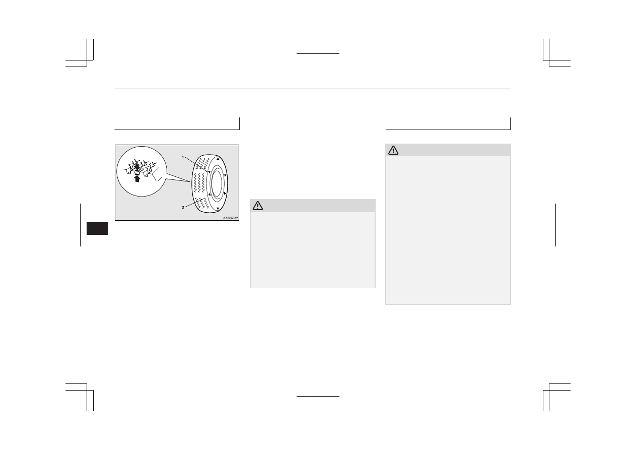
1- Location of the tread wear indicator
2- Tread wear indicator

Check  the  tyres  for  cuts,  cracks  and  other
damage.  Replace  the  tyres  if  there  are  deep
cuts  or  cracks.  Also  check  each  tyre  for
pieces of metal or pebbles.
The use of worn tyres can be very dangerous
because of the greater chance of skidding or
hydroplaning.  The  tread  depth  of  the  tyres
must exceed 1.6 mm in order for the tyres to
meet the minimum requirement for use.

Tread wear indicators will appear on the sur-
face of the tyre as the tyre wears, thereby in-
dicating  that  the  tyre  no  longer  meets  the
minimum  requirement  for  use.  When  these
wear indicators appear, the tyres must be re-
placed with new ones.
On 4-wheel drive vehicles, when replacement
of any of the tyres is necessary, replace all of
them.

CAUTION

l

Always  use  tyres  of  the  same  size,  same
type,  and  same  brand,  and  which  have  no
wear differences.
Using tyres of different size, type, brands or
degree of wear, will increase the differential
oil temperature, resulting in possible damage
to the driving system. Further, the drive train
will be subjected to excessive loading, possi-
bly  leading  to  oil  leakage,  component  seiz-
ure, or other serious faults.

Replacing tyres and wheels

E01007201514

CAUTION

l

Avoid using different size tyres from the one
listed  and  the  combined  use  of  different
types of tyres, as this can affect driving safe-
ty.
Refer  to  “Tyres  and  wheels”  on  page
11-12.

l

Even  if  a  wheel  has  the  same  rim  size  and
offset  as  the  specified  type  of  wheel,  its
shape  may  prevent  it  from  being  fitted  cor-
rectly. We recommend you to consult a spe-
cialist before using wheels that you have.

l

As your vehicle is equipped with a tyre pres-
sure monitoring system, only MITSUBISHI
MOTORS  genuine  wheels  should  be  used.
Use of another type of wheel risks air leaks
and sensor damage, as it will not be possible
to  install  the  tyre  inflation  pressure  sensors
properly.
Refer  to  “Tyre  pressure  monitoring  system
(TPMS)*” on page 6-71.

Tyres

10-14

OGAE18E1

Maintenance

10

Tyre rotation

E01001901317

Tyre  wear  varies  with  vehicle  conditions,
road  surface  conditions  and  individual  driv-
er’s driving habits. To equalize the wear and
help extend tyre life, it is recommended to ro-
tate  the  tyres  immediately  after  discovery  of
abnormal wear, or whenever the wear differ-
ence between the front and rear tyres is rec-
ognizable.

When  rotating  tyres,  check  for  uneven  wear
and  damage.  Abnormal  wear  is  usually
caused  by  incorrect  tyre  pressure,  improper
wheel alignment, out of balance wheel, or se-
vere braking. We recommend you to have it
checked  to  determine  the  cause  of  irregular
tread wear.

Spare tyre used

Spare tyre not used

Tyres that have arrows showing rotation direction

Front

Front

Front

*-  If  the  spare  tyre  wheel  differs  from  the
standard tyre wheel, do not perform tyre rota-
tion using a spare wheel.

CAUTION

l

A temporary spare tyre can be fitted tempo-
rarily  in  place  of  a  tyre  that  has  been  re-
moved during the tyre rotation. However, it
must not be included in the regular tyre rota-
tion sequence.

l

If  the  tyres  have  arrows  (A)  indicating  the
correct  direction  of  rotation,  swap  the  front
and rear tyres on the left-hand side of the ve-
hicle  and  the  front  and  rear  tyres  on  the
right-hand  side  of  the  vehicle  separately.
Keep each tyre on its original side of the ve-
hicle.  When  fitting  the  tyres,  make  sure  the
arrows  point  in  the  direction  in  which  the
wheels  will  turn  when  the  vehicle  moves
forward. Any tyre whose arrow points in the
wrong  direction  will  not  perform  to  its  full
potential.

Front

Tyres

10-15

OGAE18E1

Maintenance

10

CAUTION

l

Avoid the combined use of different types of
tyres.
Using different types of tyres can affect ve-
hicle performance and safety.

Snow tyres

E01002001852

The  use  of  snow  tyres  is  recommended  for
driving on snow and ice. To preserve driving
stability,  mount  snow  tyres  of  the  same  size
and tread pattern on all 4 wheels.
A  snow  tyre  that  is  worn  down  more  than
50% is no longer appropriate to use.
Snow tyres which do not meet specifications
must not be used.

CAUTION

l

Observe  permissible  maximum  speed  for
your snow tyres and the legal speed limit.

l

As your vehicle is equipped with a tyre pres-
sure monitoring system, only MITSUBISHI
MOTORS  genuine  wheels  should  be  used.
Use of another type of wheel risks air leaks
and sensor damage, as it will not be possible
to  install  the  tyre  inflation  pressure  sensors
properly.
Refer  to  “Tyre  pressure  monitoring  system
(TPMS)*” on page 6-71.

NOTE

l

The  laws  and  regulations  concerning  snow
tyres (driving speed, required use, type, etc.)
vary. Find out and follow the laws and regu-
lations in the area you intend to drive.

l

If  flange  nuts  are  used  on  your  vehicle,
change to tapered nuts when steel wheels are
used.

Tyre chains

E01002103394

If  tyre  chains  have  to  be  used,  ensure  that
they  are  fitted  only  on  the  drive  wheels
(front) in accordance with the manufacturer’s
instructions.
On 4WD vehicles in which the driving power
is  distributed  preferentially  to  the  front
wheels,  ensure  that  the  tyre  chains  are  fitted
on the front.
Use  only  tyre  chains  which  are  designed  for
use  with  the  tyres  mounted  on  the  vehicle:
use  of  the  incorrect  size  or  type  of  chain
could result in damage to the vehicle body.
Contact  a  MITSUBISHI  MOTORS  Author-
ized  Service  Point  before  putting  on  tyre
chains. The max. chain height is as follows.

Tyre size

Wheel size

Max. chain

height [mm]

215/70R16
215/65R16

16 x 6 1/2 J

9 mm

Tyre size

Wheel size

Max. chain

height [mm]

215/60R17

17 x 6 1/2 J

225/55R18

18x7 J

When  driving  with  tyre  chains  on  the  tyres,
do  not  drive  faster  than  50  km/h  (30  mph).
When you reach roads that are not covered in
snow, immediately remove the tyre chains.

CAUTION

l

Practice  fitting  the  chains  before  you  need
them.  Don’t  expect  help  from  other  people
in the cold.

l

Choose a clear straight stretch of road where
you can pull over and still be seen while you
are fitting the chains.

l

Do not fit chains before you need them. This
will  wear  out  your  tyres  and  the  road  sur-
face.

l

After  driving  around  100-300  metres,  stop
and retighten the chains.

l

Drive cautiously and do not exceed 50 km/h
(30 mph).
Remember  that  preventing  accidents  is  not
the purpose of tyre chains.

l

When tyre chains are installed, take care that
they do not damage the disc wheel or body.

Tyres

10-16

OGAE18E1

Maintenance

10

CAUTION

l

Do not install a tyre chain on an emergency
wheel which is compact in size. If one of the
front  wheels  has  punctured,  replace  it  with
one of the rear wheels and install the tempo-
rary spare wheel in that place before fitting a
tyre chain.

l

An  aluminium  wheel  can  be  damaged  by  a
tyre chain while driving. When fitting a tyre
chain on an aluminium wheel, take care that
any  part  of  the  chain  and  fitting  cannot  be
brought into contact with the wheel.

l

Remove the wheel covers before installing a
tyre  chain,  otherwise  they  may  be  damaged
by the tyre chain. (See page 8-20.)

l

When installing or removing the tyre chains,
take care that hands and other parts of your
body  are  not  injured  by  the  sharp  edges  of
the vehicle body.

NOTE

l

The laws and regulations concerning the use
of  tyre  chains  vary.  Always  follow  local
laws and regulations.
In most countries, it is prohibited by law to
use tyre chains on roads without snow.

Wiper blade rubber
replacement

E01002600327

Windscreen wiper blades

1. Lift the wiper arm off the windscreen.
2. Pull the wiper blade until its stopper (A)

disengages  from  the  hook  (B).  Pull  the
wiper blade further to remove it.

NOTE

l

Do not let the wiper arm drop onto the wind-
screen. This could damage the glass.

3. Attach  the  retainers  (C)  to  a  new  wiper

blade.

Refer to the illustration to ensure that the
retainers are correctly aligned as you at-
tach them.

4. Insert the wiper blade into the arm, start-

ing  with  the  opposite  end  of  the  blade
from  the  stopper.  Make  sure  the  hook
(B)  is  fitted  correctly  in  the  grooves  in
the blade.

NOTE

l

If  a  retainer  is  not  supplied  with  the  new
wiper  blade,  use  the  retainer  from  the  old
blade.

Wiper blade rubber replacement

10-17

OGAE18E1

Maintenance

10

5. Push the wiper blade until the hook (B)

engages securely with the stopper (A).

Rear window wiper blades

1. Lift the wiper arm off the window glass.
2. Pull the wiper blade downward to disen-

gage it from the stopper (A) at the end of
the wiper arm. Pull the wiper blade fur-
ther to remove it.

3. Slide  a  new  wiper  blade  through  the

hook (B) on the wiper arm.

NOTE

l

Do not allow the wiper arm to fall onto the
window glass; it could damage the glass.

4. Firmly  insert  the  retainer  (C)  into  the

groove (D) in the wiper blade.
Refer to the illustration to ensure that the
retainers are correctly aligned as you in-
sert them into the groove.

NOTE

l

If  a  retainer  is  not  supplied  with  the  new
wiper  blade,  use  the  retainer  from  the  old
blade.

General maintenance

E01002700520

Fuel, engine coolant, oil and ex-

haust gas leakage

Look under the body of your vehicle to check
for  fuel,  engine  coolant,  oil  and  exhaust  gas
leaks.

WARNING

l

If you see a suspicious fuel leak or if you
smell fuel, do not operate the vehicle; call
your  MITSUBISHI  MOTORS  Author-
ized Service Point for assistance.

Exterior and interior lamp op-

eration

Operate  the  combination  lamp  switch  to
check that all lamps are functioning properly.
If  the  lamps  do  not  illuminate,  the  probable
cause is a blown fuse or defective lamp bulb.
Check  the  fuses  first.  If  there  is  no  blown
fuse, check the lamp bulbs.
For information regarding the inspection and
replacement of the fuses and the lamp bulbs,
refer  to  “Fuses”  on  page  10-19  and  “Re-
placement of lamp bulbs” on page 10-26.

General maintenance

10-18

OGAE18E1

Maintenance

10

If the fuses and bulbs are all OK, we recom-
mend  you  to  have  your  vehicle  checked  and
repaired.

Meter, gauge and indicator/

warning lamps operation

Start  the  engine  and  check  the  operation  of
all  instruments,  gauges  and  indication  and
warning lamps.
If  there  is  anything  wrong,  we  recommend
you to have your vehicle inspected.

Hinges and latches lubrication

Check all latches and hinges, and, if necessa-
ry, have them lubricated.

For cold and snowy weather

E01002800361

Ventilation slots

The  ventilation  slots  in  front  of  the  wind-
screen  should  be  kept  clear  of  leaves  or
brushed  clear  after  heavy  snowfall,  so  that
the  operation  of  the  heating  and  ventilation
systems will not be impaired.

Weatherstripping

To  prevent  freezing  of  the  weatherstripping
on  the  doors,  bonnet,  etc.,  they  should  be
treated with silicone grease.

Additional equipment

It is a good idea to carry a shovel or a short-
handled spade in the vehicle during the win-
ter so that you can clear away snow if you get
stranded.  A  small  hand-brush  for  sweeping
snow off the vehicle and a plastic scraper for
the windscreen and rear window are also use-
ful.

Fusible links

E01002900564

The fusible links will melt to prevent a fire if
a large current attempts to flow through cer-
tain electrical systems.
In  case  of  a  melted  fusible  link,  we  recom-
mend you to have your vehicle inspected.
For  the  fusible  links,  please  refer  to  “Fuse
load capacity” on page 10-21.

WARNING

l

Fusible links must not be replaced by any
other device. Failing to fit the correct fusi-
ble  link  may  result  in  fire  in  the  vehicle,
property  destruction  and  serious  or  fatal
injuries at any time.

Fuses

E01003002250

Fuse block location

To  prevent  damage  to  the  electrical  system
due to shortcircuiting or overloading, each in-
dividual circuit is provided with a fuse.
There  are  fuse  blocks  in  the  passenger  com-
partment and in the engine compartment.

For cold and snowy weather

10-19

OGAE18E1

Maintenance

10

Passenger  compartment  (LHD

vehicles)

The  fuse  blocks  in  the  passenger  compart-
ment are located behind the fuse lid in front
of  the  driver’s  seat  at  the  position  shown  in
the illustration.

A- Main fuse block

B- Sub fuse block

1. Insert a straight blade (or minus) screw-

driver into the notch of the fuse lid and
pry gently to remove it.

2. To put back the fuse lid, line up the fuse

lid  hook  (A)  with  the  clamp  (B)  on  the
instrument  panel  and  push  the  lid  back
in.

Passenger  compartment  (RHD

vehicles)

The fuse boxes in the passenger compartment
are located behind the glove box at the posi-
tion shown in the illustration.

A- Main fuse block

B- Sub fuse block

Main fuse block

1. Open the glove box.

Fuses

10-20

OGAE18E1

Maintenance

10

2. Move the rod (A) on the left side of the

glove box to the left side of the box.

3. While pressing the side of the glove box,

unhook the left and right hooks (B) and
lower the glove box.

4. Remove the glove box fastener, and then

remove the glove box.

Sub fuse block

1. Remove  the  cover  from  the  bottom  of

the glove box.

Engine compartment

In the engine compartment, the fuse block is
located as shown in the illustration.

1- Push the knob.
2- Remove the cover.

Fuse load capacity

E01007701968

The fuse capacity and the names of electrical
systems  protected  by  the  fuses  are  indicated
on the inside of the fuse lid (LHD vehicles),
the  inside  of  the  glove  box  (RHD  vehicles)
and inside of the fuse block cover (inside of
the engine compartment).

Fuses

10-21

OGAE18E1

Maintenance

10

Passenger compartment fuse lo-

cation table

NOTE

l

Spare  fuses  are  provided  on  the  lid  of  the
fuse  block  in  the  engine  compartment.  Al-
ways use a fuse of the same capacity for re-
placement.

Passenger compartment fuse location (LHD)

Main fuse block

Sub fuse block

Passenger compartment fuse location (RHD)

Sub fuse block

Main fuse block

No.

Sym-

bol

Electrical sys-

tem

Ca-

paci-

ties

1

Heater

30 A

*1

2

Stop lamps

(Brake lamps)

15 A

*1

: Fusible link

*2

: Even if your vehicle is equipped with the

rear fog lamp, the fuse of the rear fog lamp
may not be installed on your vehicle.

No.

Sym-

bol

Electrical sys-

tem

Ca-

paci-

ties

3

Rear fog lamp

10 A 

*2

4

Windscreen

wipers

30 A

5

Option

10 A

6

Door locks

20 A

7

Radio

15 A

8

Control unit re-

lay

7.5 A

9

Interior lamps

(Room lamps)

15 A

10

Hazard warning

flasher

15 A

11

Rear window

wiper

15 A

12

Instruments

7.5 A

13

Cigarette lighter/

Accessory sock-

et

15 A

*1

: Fusible link

*2

: Even if your vehicle is equipped with the

rear fog lamp, the fuse of the rear fog lamp
may not be installed on your vehicle.

Fuses

10-22

OGAE18E1

Maintenance

10

No.

Sym-

bol

Electrical sys-

tem

Ca-

paci-

ties

14

Ignition switch

10 A

15

Sunroof

20 A

16

Outside rear-

view mirrors

10 A

17

4-wheel drive

system

10 A

18

Reversing lamps

(Backup lamps)

7.5 A

19

Accessory sock-

et

15 A

20

Electric window

control

30 A

*1

21

Rear window

demister

30 A

*1

22

Heated door

mirror

7.5 A

23

Passenger’s

power seat

25 (20)

A

*1

: Fusible link

*2

: Even if your vehicle is equipped with the

rear fog lamp, the fuse of the rear fog lamp
may not be installed on your vehicle.

No.

Sym-

bol

Electrical sys-

tem

Ca-

paci-

ties

24

Driver’s power

seat

25 (20)

A

25

Heated seat

30 A

*1

: Fusible link

*2

: Even if your vehicle is equipped with the

rear fog lamp, the fuse of the rear fog lamp
may not be installed on your vehicle.

l

Some fuses may not be installed on your
vehicle, depending on the vehicle model
or specifications.

l

The  table  above  shows  the  main  equip-
ment corresponding to each fuse.

Engine  compartment  fuse  loca-

tion table

Engine compartment fuse location

Behind of the fuse block cover

No.

Sym-

bol

Electrical sys-

tem

Ca-

paci-

ties

1

Front fog lamps

15 A

2

Engine

7.5 A

*1

: Fusible link

Fuses

10-23

OGAE18E1

Maintenance

10

No.

Sym-

bol

Electrical sys-

tem

Ca-

paci-

ties

3

Automatic trans-

mission

20 A

4

Horn

10 A

5

Alternator

7.5 A

6

Headlamp wash-

er

20 A

7

Air conditioning

10 A

8

ETV/Oil cooler

fan

(Twin Clutch

SST)

15 A

9

Security horn

20 A

10

Wiper de-icer

15 A

11

12

Electric tailgate

30 A

13

Daytime running

lamps

10 A

14

Headlamp high-

beam (left)

10 A

15

Headlamp high-

beam (right)

10 A

*1

: Fusible link

No.

Sym-

bol

Electrical sys-

tem

Ca-

paci-

ties

16

Head-

lamp

low

beam

(left)

Dis-

charge

20 A

17

Head-

lamp

low

beam

(right)

Dis-

charge

20 A

18

Head-

lamp

low

beam

(left)

Halo-

gen

10 A

19

Head-

lamp

low

beam

(right)

Halo-

gen

10 A

20

ENG/POWER

10 A

21

Ignition coil

10 A

22

ENG/POWER

20 A

*1

: Fusible link

No.

Sym-

bol

Electrical sys-

tem

Ca-

paci-

ties

Fuel line heater

25 A

23

Fuel pump

15 A

24

Starter

30 A

*1

25

26

Anti-lock brake

system

40 A

*1

27

Anti-lock brake

system

30 A

*1

28

Air conditioning

condenser fan

motor

30 A

*1

29

Radiator fan mo-

tor

40 A

*1

30

IOD

IOD

30 A

31

Audio system

amp

30 A

32

Diesel

30 A

33

Spare fuse

10 A

34

Spare fuse

15 A

35

Spare fuse

20 A

*1

: Fusible link

Fuses

10-24

OGAE18E1

Maintenance

10

l

Some fuses may not be installed on your
vehicle, depending on the vehicle model
or specifications.

l

The  table  above  shows  the  main  equip-
ment corresponding to each fuse.

The  fuse  box  does  not  contain  spare  7.5  A,
25  A  or  30  A  fuses.  If  one  of  these  fuses
burns out, substitute with the following fuse.
7.5 A: 10 A spare fuse
25 A: 20 A spare fuse
30 A: 30 A audio system amp fuse
When using a substitute fuse, replace with a
fuse of the correct capacity as soon as possi-
ble.

Identification of fuse

Capacity

Colour

7.5 A

Brown

10 A

Red

15 A

Blue

20 A

Yellow

25 A

Natural (White)

30 A

Green (fuse type)/Pink

(fusible link type)

40 A

Green (fusible link type)

Fuse replacement

E01007800630

1. Before replacing a fuse, always turn off

the  electrical  circuit  concerned  and  turn
the ignition switch to the “LOCK” posi-
tion or put the operation mode in OFF.

2. Remove the fuse puller (A) from the in-

side  of  the  fuse  box  in  the  engine  com-
partment.

3. Referring to the fuse load capacity table,

check the fuse pertaining to the problem.

B- Fuse is OK
C- Blown fuse

NOTE

l

If any system does not function but the fuse
corresponding to that system is normal, there
may be a fault in the system elsewhere. We
recommend  you  to  have  your  vehicle
checked.

4. Use  the  fuse  puller  to  insert  a  new  fuse

with  the  same  capacity.  Make  sure  you
insert  the  fuse  into  the  same  location  in
the fuse block.

Fuses

10-25

OGAE18E1

Maintenance

10

CAUTION

l

If the newly inserted fuse blows again after a
short  time,  we  recommend  you  to  have  the
electrical  system  checked  to  find  the  cause
and rectify it.

l

Never use a fuse with a larger capacity than
specified  or  a  substitute  (such  as  a  cable  or
foil). Doing so could cause the circuit wires
to overheat and create a fire.

Replacement of lamp bulbs

E01003102248

Before  replacing  a  bulb,  ensure  the  lamp  is
off.  Do  not  touch  the  glass  part  of  the  new
bulb  with  your  bare  fingers;  the  skin  oil  left
on  the  glass  will  evaporate  when  the  bulb
gets hot and the vapour will condense on the
reflector and dim the surface.

CAUTION

l

Bulbs  are  extremely  hot  immediately  after
being turned off.
When  replacing  a  bulb,  wait  for  it  to  cool
sufficiently  before  touching  it.  You  could
otherwise be burnt.

l

Do not install commercially available LED-
type bulbs.
Commercially  available  LED-type  bulbs
could  adversely  affect  the  operation  of  the
vehicle, such as by preventing the lamps and
other  vehicle  equipment  from  operating
properly.

NOTE

l

If  you  are  unsure  of  how  to  carry  out  the
work  as  required,  we  recommend  you  to
consult a specialist.

l

Be  careful  not  to  scratch  the  vehicle  body
when removing a lamp or lens.

l

When it rains or when the vehicle has been
washed, the inside of the lens sometimes be-
comes foggy. This is the same phenomenon
as when window glass mists up on a humid
day, and does not indicate a functional prob-
lem.
When the lamp is switched on, the heat will
remove  the  fog.  However,  if  water  gathers
inside the lamp, we recommend you to have
the lamp checked.

Bulb location and capacity

E01003201574

CAUTION

l

When replacing a bulb, be sure to use a new
bulb of the same type, wattage and colour. If
you  install  a  different  bulb,  the  bulb  could
malfunction  or  fail  to  come  on  and  could
lead to a vehicle fire.

Outside

E01003305267

Front

1- Front  turn-signal  lamps:  21  W

(WY21W)

2- Headlamps, high-beam: 60 W (HB3)
3- Daytime running lamps

*1

Position lamps (Type 2)

*2

4- Front fog lamps

*1

: 35 W (H8)

*1 

If so equipped

Replacement of lamp bulbs

10-26

OGAE18E1

Maintenance

10

5- Headlamps,  low  beam  Halogen:  55  W

(H11)
High intensity discharge

*2

: 35 W (D2S)

5 W (W5W)

6- Position lamps: (Type 1)

*1

 5 W (W5W)

7- Side turn-signal lamps (on fender)

*1

*2

:

5 W

8- Side  turn-signal  lamps  (on  outside  rear-

view mirror)

*1

Codes  in  parentheses  indicate  bulb
types.

WARNING

l

Check  with  a  MITSUBISHI  MOTORS
Authorized Service Point when it is neces-
sary  to  repair  a  high  intensity  discharge
headlamp or to replace the bulb.
High  voltage  is  generated  in  the  high  in-
tensity discharge headlamp bulb and elec-
trodes,  which  may  cause  a  severe  shock
when the bulb and connector are removed
or disconnected.

*2 

Have  the  lamps  bulbs  replaced  at  a

MITSUBISHI 

MOTORS 

Authorized

Service Point.

*1 

If so equipped

NOTE

l

An LED, not a bulb, is used in the daytime
running lamp/position lamp (Type 2) and the
side  turn-signal  lamp  (on  the  outside  rear-
view mirror).
Contact  a  MITSUBISHI  MOTORS  Author-
ized  Service  Point  when  there  is  a  need  for
repair or replacement.

l

For the side turn-signal lamp (on fender), it
is  not  possible  to  repair  or  replace  just  the
bulb.
Contact  a  MITSUBISHI  MOTORS  Author-
ized  Service  Point  when  there  is  a  need  for
repair or replacement.

Rear

9- High-mounted stop lamp

10- Licence plate lamps: 5 W (W5W)
11- Rear fog lamp
12- Reversing lamps: 16 W (W16W)
13- Rear turn-signal lamps: 21 W (W21W)
14- Stop and tail lamps

Codes  in  parentheses  indicate  bulb
types.

NOTE

l

An LED, not a bulb, is used in the stop and
tail  lamp,  the  high-mounted  stop  lamp  and
the rear fog lamp.
Contact  a  MITSUBISHI  MOTORS  Author-
ized  Service  Point  when  there  is  a  need  for
repair or replacement.

Inside

E01003403570

1- Room lamp (rear)*: 8 W
2- Vanity mirror lamps*: 2 W
3- Room lamp (front) & map lamps: 8 W
4- Luggage room lamp: 5 W
5- Glove box lamp: 1.4 W

*: If so equipped

Replacement of lamp bulbs

10-27

OGAE18E1

Maintenance

10

Headlamps (low beam, except

for vehicles with high intensity

discharge headlamps)

E01009301522

1. When replacing the bulb on the left side

of the vehicle in the case of diesel-pow-
ered vehicles, remove the bolt (A) hold-
ing down the relay box and move the re-
lay box towards the rear of the vehicle.

*: Front of the vehicle

2. When  replacing  the  bulb  on  the  right

side of the vehicle in the case of diesel-
powered  vehicles  (1600  models  only),
remove the bolts (B), and then move the
reserve tank.

*: Front of the vehicle

3. When  replacing  the  bulb  on  the  right

side of the vehicle in the case of diesel-
powered  vehicles,  remove  the  clips  (C)
by  prying  with  a  straight  blade  (or  mi-
nus)  screwdriver,  and  remove  the  side
cover.

*: Front of the vehicle

4. Turn  the  cap  (D)  anticlockwise  to  re-

move it.

*: Front of the vehicle

5. Turn  the  bulb  (E)  anticlockwise  to  re-

move it.

*: Front of the vehicle

Replacement of lamp bulbs

10-28

OGAE18E1

Maintenance

10

6. While holding down the tab (F), pull out

the socket (G).

7. To install the bulb, perform the removal

steps in reverse.

CAUTION

l

Handle  halogen  lamp  bulbs  with  care.  The
gas inside halogen lamp bulbs is highly pres-
surized, so dropping, knocking, or scratching
a halogen lamp bulb can cause it to shatter.

l

Never  hold  the  halogen  lamp  bulb  with  a
bare hand, dirty glove, etc.
The oil from your hand could cause the bulb
to break the next time the headlamps are op-
erated.
If  the  glass  surface  is  dirty,  it  must  be
cleaned with alcohol, paint thinner, etc., and
refit it after drying it thoroughly.

Headlamps (low beam, for ve-

hicles with high intensity dis-

charge headlamps)

E01010101214

Do not attempt to disassemble or repair head-
lamps,  and  do  not  attempt  to  replace  their
bulbs.

WARNING

l

Check  with  a  MITSUBISHI  MOTORS
Authorized Service Point when it is neces-
sary  to  repair  a  high  intensity  discharge
headlamp or to replace the bulb.
High  voltage  is  generated  in  the  high  in-
tensity discharge headlamp bulb and elec-
trodes,  which  may  cause  a  severe  shock
when the bulb and connector are removed
or disconnected.

Headlamps (High-beam)

E01009400135

1. When replacing the bulb on the left side

of the vehicle in the case of diesel-pow-
ered vehicles, remove the bolt (A) hold-
ing down the relay box and move the re-
lay box towards the rear of the vehicle.

*: Front of the vehicle

Replacement of lamp bulbs

10-29

OGAE18E1

Maintenance

10


Content   ..  23  24  25  26   ..