Mitsubishi Galant (2004+). Manual - part 198
EMISSION CONTROL
TSB Revision
ENGINE AND EMISSION CONTROL
17-83
VACUUM HOSE CHECK
M1173007300171
1. Using the VACUUM HOSE ROUTING diagram as a guide,
check that the vacuum hoses are correctly connected.
2. Check the connection of the vacuum hoses, (removed,
loose, etc.) and confirm that there are no sharp bends or
damage.
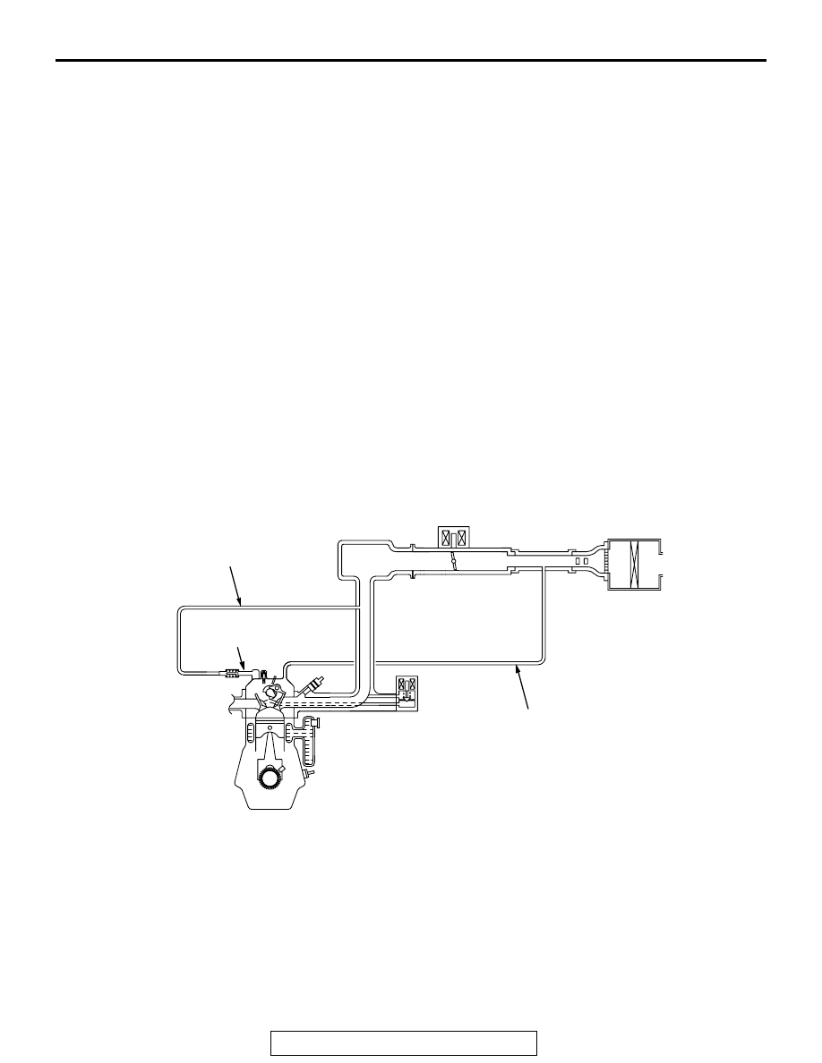
POSITIVE CRANKCASE VENTILATION SYSTEM
GENERAL DESCRIPTION (POSITIVE CRANKCASE VENTILATION SYSTEM)
M1173005000293
The positive crankcase ventilation (PCV) system pre-
vents the escape of blow-by gases from inside the
crankcase into the atmosphere.
Fresh air is sent from the air cleaner into the crank-
case through the breather hose to be mixed with the
blow-by gas inside the crankcase.
The blow-by gas inside the crankcase is drawn into
the intake manifold through the PCV valve.
The PCV valve is designed to lift the plunger accord-
ing to the intake manifold vacuum so as to regulate
the flow of blow-by gas properly.
In other words, the blow-by gas flow is regulated dur-
ing low load engine operation to maintain engine sta-
bility, while the flow is increased during high load
operation to improve the ventilation performance.
SYSTEM DIAGRAM
<2.4L ENGINE>
AK300553
VENTILATION HOSE
POSITIVE CRANKCASE
VENTILATION VALVE
BREATHER HOSE
AB