Content .. 1583 1584 1585 1586 ..
Mitsubishi Galant 9G. Manual - part 1585
RADIO WITH CD PLAYER
TSB Revision
CHASSIS ELECTRICAL
54A-212
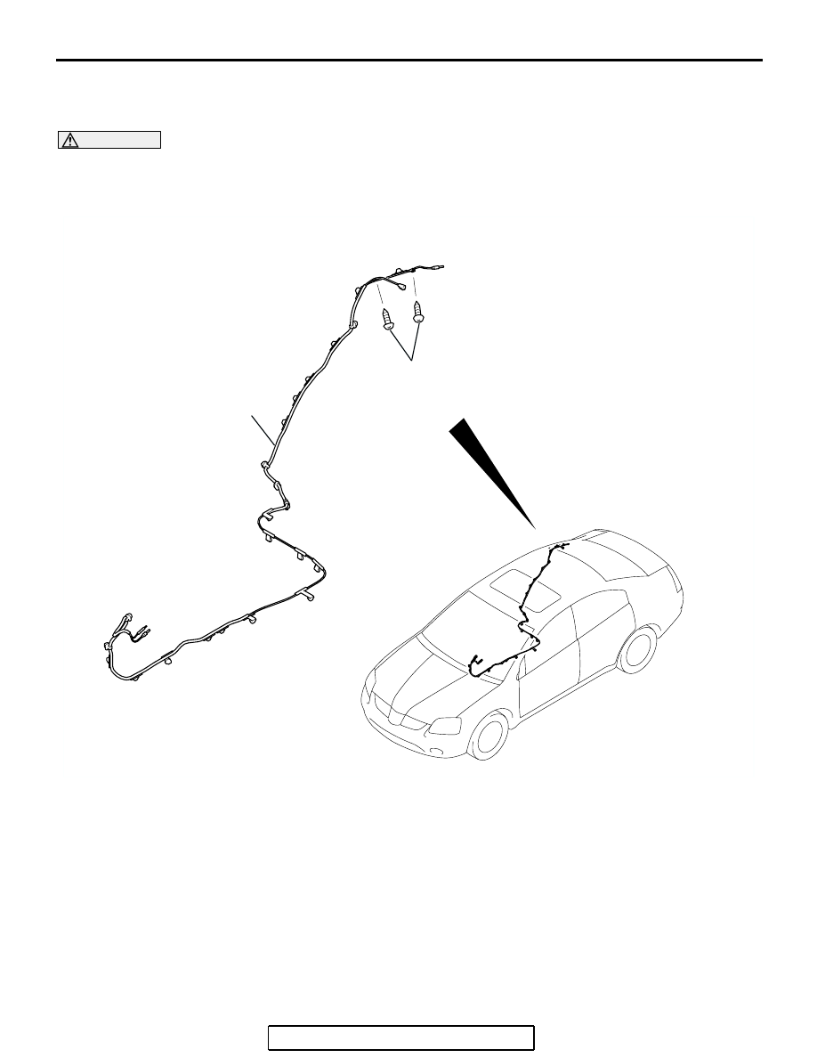
ANTENNA
REMOVAL AND INSTALLATION
M1544002900712
WARNING
When removing and installing the passenger seat, be sure to carry out advanced air bag spe-
cial function (accuracy testing and calibration) after the seat has been installed in the vehi-
cle. (Refer to GROUP 52B, On-Vehicle Service
AC306706
1
1.5 ± 0.5 N·m
14 ± 4 in-lb
AB
REMOVAL STEPS
• REAR SEAT CUSHION ASSEMBLY
(GROUP 52A, REAR SEAT ASSEMBLY
.)
• REAR SCUFF PLATE, FRONT DOOR
OPENING TRIM (CENTER PILLAR
SIDE), REAR DOOR OPENING TRIM
(CENTER PILLAR SIDE), FRONT
SCUFF PLATE (REFER TO GROUP
52A, TRIMS
• FRONT SEAT BELT UPPER AND
LOWER CONNECTION (REFER TO
GROUP 52A, FRONT SEAT BELT
.)
• CENTER PILLAR TRIM LOWER, COWL
SIDE TRIM (REFER TO GROUP 52A,
TRIMS
• GEARSHIFT LEVER PANEL, FRONT
BOX, FLOOR CONSOLE ASSEMBLY
(REFER TO GROUP 52A, FLOOR
CONSOLE ASSEMBLY
.)
• FRONT SEAT ASSEMBLY (REFER TO
GROUP 52A, FRONT SEAT ASSEMBLY
• TRUNK LID RELEASE HANDLE
COVER (REFER TO GROUP 42,
TRUNK LID
REMOVAL STEPS (Continued)