Mitsubishi Evolution X. Manual - part 813
 

  Index      Mitsubishi     Mitsubishi Evolution X - service repair manual 2008 year


Search            


Content   ..  811  812  813  814   ..


Mitsubishi Evolution X. Manual - part 813


DIAGNOSIS

TSB Revision

ACTIVE SKID CONTROL SYSTEM (ASC)

35C-259

CHECK AT ECU TERMINALS

M1355001700191

.

TERMINAL VOLTAGE CHECK

Required Special Tool:
MB991997: ASC Check Harness
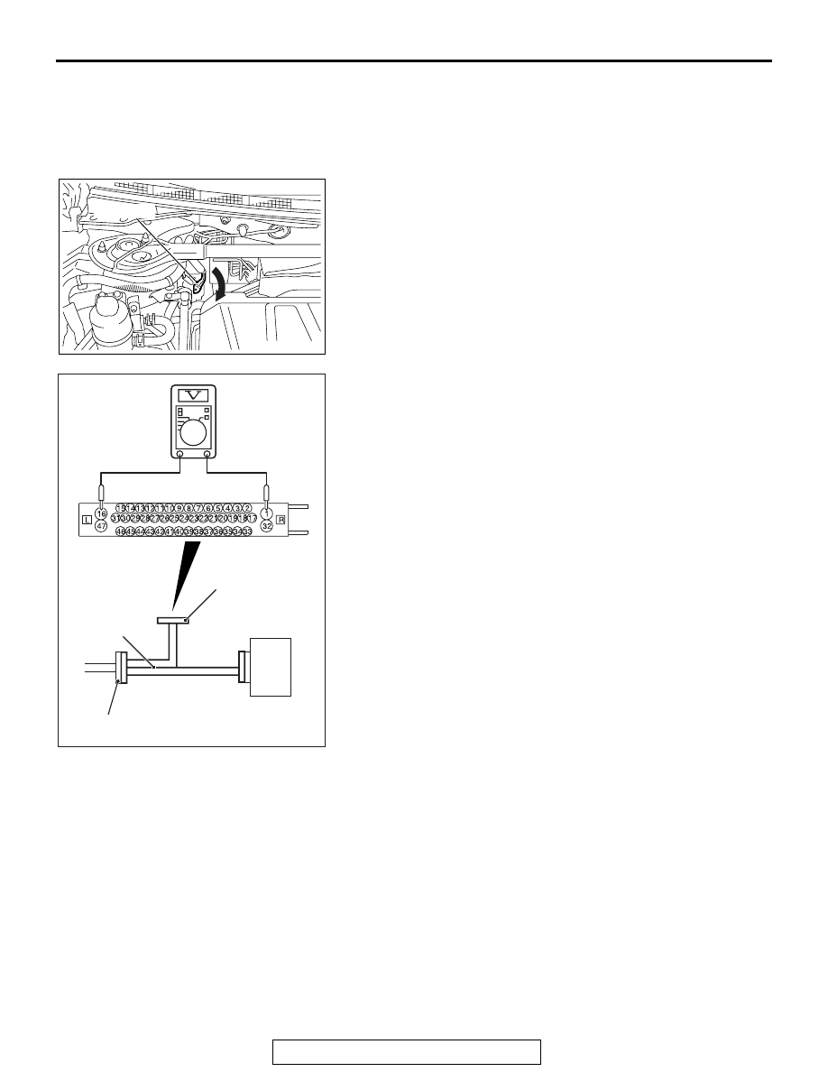
1. Operate the lock lever as shown in the figure to disconnect 

the ASC-ECU wiring harness connector.

2. Connect special tool ASC Check Harness (MB991997) to 

measure the voltage between each check connector 
terminal and the ground terminal (No. 16 or 47).

AC708791

AB

Lock lever

AC401192 AG

ASC-ECU

MB991997

A-05 ASC-ECU 
harness connector

Check harness

DIAGNOSIS

TSB Revision

ACTIVE SKID CONTROL SYSTEM (ASC)

35C-260

.

RESISTANCE AND CONTINUITY BETWEEN 
HARNESS-SIDE CONNECTOR TERMINALS

Required Special Tool:
MB991997: ASC Check Harness
1. Operate the lock lever as shown in the figure to disconnect 

the ASC-ECU wiring harness connector.

Terminal 
No.

Check item

Check conditions

Normal 
conditions

1

Motor power supply

Ignition switch: ON (OFF)

Approximately 
battery voltage

2

ASC-ECU power supply

Ignition switch: ON (OFF)

Approximately 
battery voltage

22

G and yaw rate sensor power 
supply

Ignition switch: ON

Approximately 
battery voltage

32

Solenoid valve power supply

Ignition switch: ON (OFF)

Approximately 
battery voltage

34

Wheel speed sensor (FR) power 
supply

Ignition switch: ON

Approximately 
battery voltage

36

Wheel speed sensor (RL) power 
supply

Ignition switch: ON

Approximately 
battery voltage

43

Wheel speed sensor (RR) power 
supply

Ignition switch: ON

Approximately 
battery voltage

45

Wheel speed sensor (FL) power 
supply

Ignition switch: ON

Approximately 
battery voltage

AC708791

AB

Lock lever

DIAGNOSIS

TSB Revision

ACTIVE SKID CONTROL SYSTEM (ASC)

35C-261

2. When performing the continuity check, turn the ignition 

switch to LOCK (OFF) position, connect special tool ASC 
Check Harness (MB991997) as shown in the figure, and 
disconnect the ASC-ECU connector.

3. Check for continuity between terminals shown in the chart 

below.

4. Terminal layout is shown in the figure.

AC400817CO

ASC-ECU

MB991997

A-05 ASC-ECU 
harness connector

Check harness

Terminal No.

Signal

Normal conditions

16 

− body ground

Ground

Continuity exists (2 

Ω or 

less)

47 

− body ground

Ground

Continuity exists (2 

Ω or 

less)

SPECIAL TOOLS

TSB Revision

ACTIVE SKID CONTROL SYSTEM (ASC)

35C-262

SPECIAL TOOLS

M1355005800101

Tool

Tool number and 
name

Supersession

Application

MB991958

a. MB991824
b. MB991827
c. MB991910
d. MB991911
e. MB991914
f. MB991825
g. MB991826

M.U.T.-III sub 
assembly

a. Vehicle 

communication 
interface (V.C.I.)

b. M.U.T.-III USB 

cable

c. M.U.T.-III main 

harness A 
(Vehicles with 
CAN 
communication 
system)

d. M.U.T.-III main 

harness B 
(Vehicles without 
CAN 
communication 
system)

e. M.U.T.-III main 

harness C (for 
Daimler Chrysler 
models only)

f. M.U.T.-III 

measurement 
adapter

g. M.U.T.-III trigger 

harness

MB991824-KIT
NOTE: G: MB991826 
M.U.T.-III Trigger 
Harness is not 
necessary when 
pushing V.C.I. ENTER 
key.

CAUTION

M.U.T.-III main harness A 
(MB991910) should be used. 
M.U.T.-III main harness B and C 
should not be used for this 
vehicle.
ASC check (Diagnostic trouble 
code display, service data display 
and calibration by scan tool )

MB991997

ASC check harness

Voltage inspection at ASC-ECU 
terminals

MB991910

MB991826

MB991958

MB991911

MB991914

MB991824

MB991827

MB991825

DO NOT USE

a

b

c

d

e

f

g

DO NOT USE

MB991997


Content   ..  811  812  813  814   ..