Mitsubishi Evolution X. Manual - part 814
ON-VEHICLE SERVICE
TSB Revision
ACTIVE SKID CONTROL SYSTEM (ASC)
35C-263
ON-VEHICLE SERVICE
HYDRAULIC UNIT CHECK
M1355006100138
Required Special Tools:
• MB991958: M.U.T.-III Sub Assembly
• MB991824: Vehicle Communication Interface (V.C.I.)
• MB991827: M.U.T.-III USB Cable
• MB991910: M.U.T.-III Main Harness A (Vehicles with
CAN communication system)
1. Raise the vehicle using a jack and support the specified
points with a rigid rack.
CAUTION
Before connecting or disconnecting scan tool, always turn
the ignition switch to the LOCK (OFF) position.
2. Before setting scan tool, turn the ignition key to the LOCK
(OFF) position.
3. With the M/T vehicles, check that the shift lever is in the
neutral position. With the TC-SST vehicle, check that the
selector lever is in the "N" position. Then, start the engine of
the vehicle.
MB991223
a. MB991219
b. MB991220
c. MB991221
d. MB991222
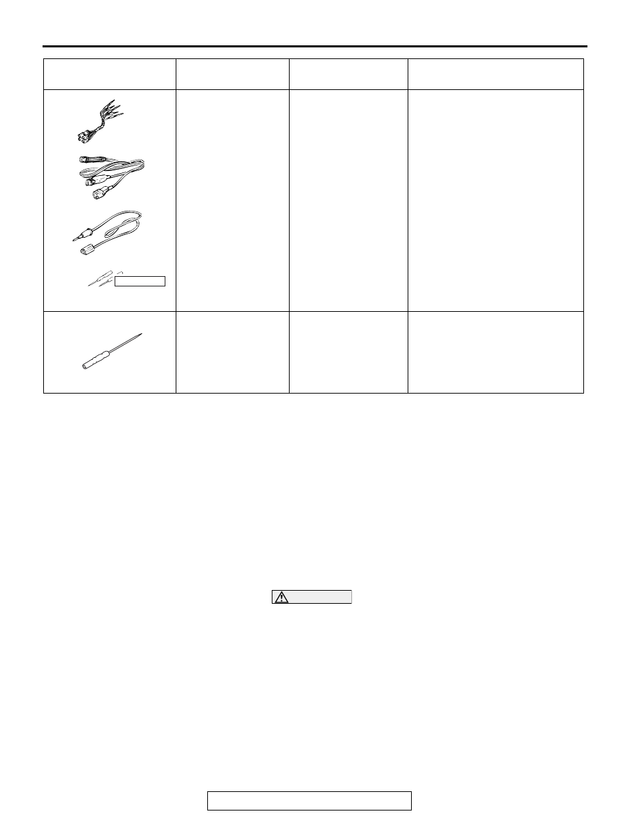
Harness set
a. Test harness
b. LED harness
c. LED harness
adaptor
d. Probe
General service tools Continuity check and voltage
measurement at harness wire or
connector for loose, corroded or
damaged terminals, or terminals
pushed back in the connector.
a. Connector pin contact
pressure inspection
b. Power circuit inspection
c. Power circuit inspection
d. Commercial tester connection
MB992006
Extra fine probe
−
Continuity check and voltage
measurement at harness wire or
connector for loose, corroded or
damaged terminals, or terminals
pushed back in the connector.
Tool
Tool number and
name
Supersession
Application
MB991223
a
d
c
b
DO NOT USE
BA
MB992006