Mitsubishi Lancer Evolution IX. Manual - part 662
 

  Index      Mitsubishi     Mitsubishi Lancer Evolution IX - service repair manual


Search            


Content   ..  660  661  662  663   ..


Mitsubishi Lancer Evolution IX. Manual - part 662


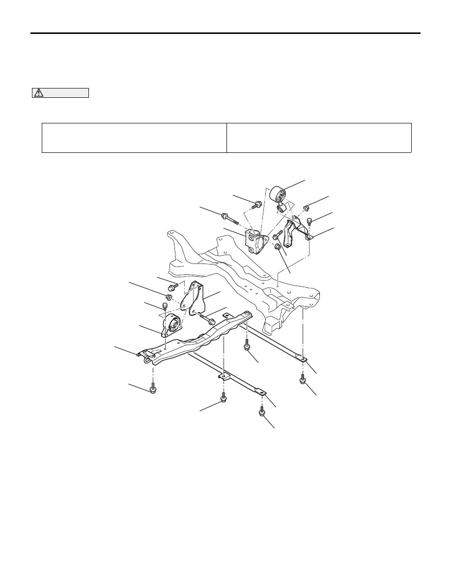
ENGINE ROLL STOPPER, CENTREMEMBER

POWER PLANT MOUNT

32-7

ENGINE ROLL STOPPER, CENTREMEMBER

REMOVAL AND INSTALLATION

M1321002300362

<LH DRIVE VEHICLES>

CAUTION

*: Indicates parts which should be initially tightened, and then fully tightened after placing the vehicle 
horizontally and loading the full weight of the engine on the vehicle body.

Pre-removal Operation
• Under Cover Removal (Refer to GROUP 51, Front 

Bumper 

P.51-2

).

Post-installation Operation
• Under Cover Installation (Refer to GROUP 51, Front 

Bumper 

P.51-2

).

AC210447

49 ± 10 N·m

AB

1

10

9

8

7

6

5

4

3

2

1

49 ± 10 N·m

49 ± 10 N·m

69 ± 10 N·m

69 ± 10 N·m

45 ± 5 N·m* 

45 ± 5 N·m* 

52 ± 7 N·m* 

70 ± 10 N·m

52 ± 7 N·m*

70 ± 10 N·m

52 ± 7 N·m*

Front roll stopper bracket and 
centremember removal steps 

1.

Front axle crossmember bars

2.

Engine front roll stopper bracket 
bolt

3.

Front suspension centremember

>>

A

<< 4.

Engine front roll stopper bracket

5.

Transmission case front roll 
stopper bracket

Rear roll stopper rod removal 
steps 

6.

Engine rear roll stopper rod bolt

7.

Transmission case rear roll 
stopper bracket

8.

Engine rear roll stopper rod bolt

9.

Engine rear roll stopper rod 
bracket

10. Engine rear roll stopper rod

ENGINE ROLL STOPPER, CENTREMEMBER

POWER PLANT MOUNT

32-8

<RH DRIVE VEHICLES>

CAUTION

*: Indicates parts which should be initially tightened, and then fully tightened after placing the vehicle 
horizontally and loading the full weight of the engine on the vehicle body.

Pre-removal Operation
• Under Cover Removal (Refer to GROUP 51, Front 

Bumper 

P.51-2

).

Post-installation Operation
• Under Cover Installation (Refer to GROUP 51, Front 

Bumper 

P.51-2

).

AC310765

1

7

6

5

4

3

1

49 ± 10 N·m

49 ± 10 N·m

69 ± 10 N·m

69 ± 10 N·m

45 ± 5 N·m* 

45 ± 5 N·m* 

70 ± 10 N·m

52 ± 7 N·m*

70 ± 10 N·m

AB

8

49 ± 10 N·m

52 ± 7 N·m* 

2

Front roll stopper bracket and 
centremember removal steps 

1.

Front axle crossmember bars

2.

Engine front roll stopper bracket 
bolt

3.

Front suspension centremember

>>

A

<< 4.

Engine front roll stopper bracket

5.

Transmission case front roll 
stopper bracket

Rear roll stopper rod removal 
steps 

6.

Engine rear roll stopper bolt

7.

Transmission case rear roll 
stopper bracket

8.

Engine rear roll stopper bracket

ENGINE ROLL STOPPER, CENTREMEMBER

POWER PLANT MOUNT

32-9

INSTALLATION SERVICE POINT
>>A<< ENGINE FRONT ROLL STOPPER 
BRACKET INSTALLATION

AC210448

Hole

Front of vehicle

AB

Install the front roll stopper so that its hole points 
towards the front side of the vehicle.

INSPECTION

M1321002400080

• Check the engine roll stopper insulators for 

cracks, separation or deformation.

CROSSMEMBER

POWER PLANT MOUNT

32-10

CROSSMEMBER

REMOVAL AND INSTALLATION

M1321003200443

<LH drive vehicles>

CAUTION

• Before removing the steering wheel and air bag module assembly, always refer to GROUP 52B - 

Service Precautions, Air bag Module and Clock Spring. Also, set the front wheels so that they are 
facing straight forward, and remove the ignition key. If you fail to do this, the SRS clock spring will 
be damaged, causing the SRS air bag to be inoperative and serious injury.

• *

1

: Indicates parts which should be initially tightened, and then fully tightened after placing the 

vehicle horizontally and loading the full weight of the engine on the vehicle body.

• *

2

: Indicates parts which should be temporarily tightened, and then fully tightened with the vehicle 

on the ground in the unladen condition.

• If the vehicle is equipped with the Brembo disc brake, during maintenance, take care not to con-

tact the parts or tools to the caliper because the paint of caliper will be scratched.

Pre-removal and Post-installation Operation
• Under Cover Removal (Refer to GROUP 51, Front 

Bumper 

P.51-2

).

• Front Axle Crossmember Bar, Front Suspension Center-

member Removal (Refer to 

P.32-7

).

• Front Exhaust Pipe Removal (Refer to GROUP 15, 

Exhaust Pipe and Main Muffler 

P.15-13

).

• Steering Wheel Air Bag Module Assembly Removal 

(Refer to GROUP 37, Steering Wheel 

P.37-13

).

• Power Steering Fluid Draining (Refer to GROUP 37, 

On-vehicle Service 

− Fluid Replacement 

P.37-10

).

Pre-removal and Post-installation Operation
• Front Exhaust Pipe Installation (Refer to GROUP 15, 

Exhaust Pipe and Main Muffler 

P.15-13

).

• Front Axle Crossmember Bar, Front Suspension Center-

member Installation (Refer to 

P.32-7

).

• Steering Wheel Air Bag Module Assembly Installation 

(Refer to GROUP 37, Steering Wheel 

P.37-13

).

• Power Steering Fluid Supplying (Refer to GROUP 37, 

On-vehicle Service 

− Fluid Replacement 

P.37-10

).

• Power Steering Fluid Line Bleeding (Refer to GROUP 37, 

On-vehicle Service 

− Power Steering System Air Bleeding 

P.37-10

).

• Press the dust cover with a finger to check whether the 

dust cover cracked or damaged.

• Checking Steering Wheel Position with Wheels Straight 

Ahead.

• Front Wheel Alignment Check and Adjustment (Refer to 

GROUP 37, On-vehicle Service 

− Steering Angle Check 

P.37-8

).

• Under Cover Installation (Refer to GROUP 51, Front 

Bumper 

P.51-2

).


Content   ..  660  661  662  663   ..