Mitsubishi Lancer Evolution IX. Manual - part 660
 

  Index      Mitsubishi     Mitsubishi Lancer Evolution IX - service repair manual


Search            


Content   ..  658  659  660  661   ..


Mitsubishi Lancer Evolution IX. Manual - part 660


RADIATOR

ENGINE COOLING

14-25

REMOVAL SERVICE POINTS
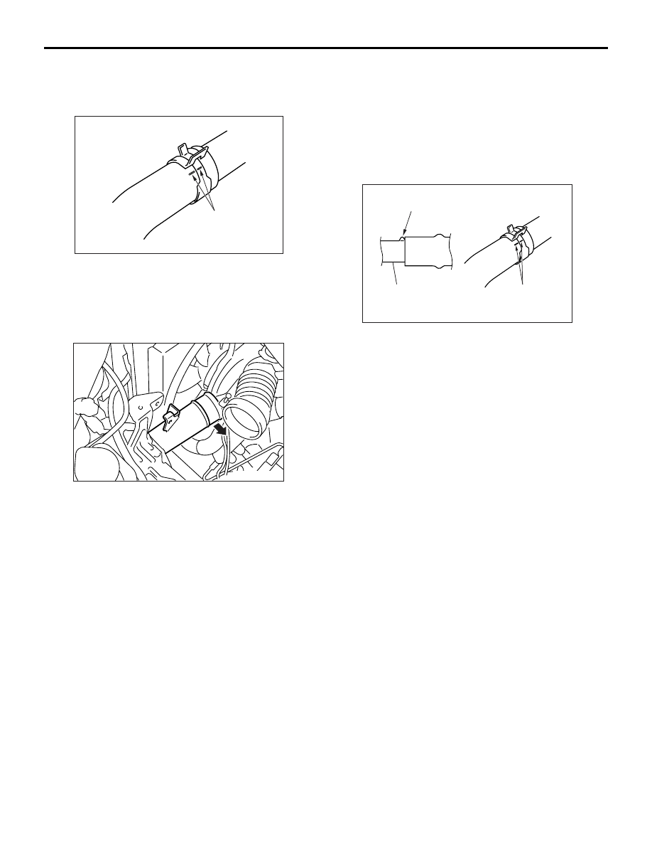
<<A>> RADIATOR UPPER HOSE/RADIA-
TOR LOWER HOSE DISCONNECTION

AC200641AB

Mating marks

Make mating marks on the radiator hose and the 
hose clamp. Disconnect the radiator hose.

<<B>> AIR PIPE B MOUNTING BOLT 
REMOVAL

AC210705

After removing the bolt, position air pipe B out of the 
way so that the pipe does not interfere with the radia-
tor assembly or the cooling fan motor, the fan and 
shroud assembly.

INSTALLATION SERVICE POINT
>>A<< RADIATOR LOWER HOSE/RADIA-
TOR UPPER HOSE CONNECTION

AC200642

Mating marks

Projection

Water inlet pipe,
water outlet fitting
or radiator

AC

1. Insert each hose as far as the projection of the 

water inlet pipe, water outlet fitting or radiator.

2. Align the mating marks on the radiator hose and 

hose clamp, and then connect the radiator hose.

NOTES

32-1

GROUP 32

POWER PLANT


MOUNT

CONTENTS

GENERAL INFORMATION . . . . . . . .

32-2

SPECIAL TOOL . . . . . . . . . . . . . . . . .

32-4

ENGINE MOUNTING . . . . . . . . . . . . .

32-4

REMOVAL AND INSTALLATION . . . . . . . . 

32-4

INSPECTION  . . . . . . . . . . . . . . . . . . . . . . . 

32-5

TRANSMISSION MOUNTING . . . . . .

32-5

REMOVAL AND INSTALLATION . . . . . . . . 

32-5

INSPECTION  . . . . . . . . . . . . . . . . . . . . . . . 

32-6

ENGINE ROLL STOPPER, 


CENTREMEMBER . . . . . . . . . . . . . . .

32-7

REMOVAL AND INSTALLATION  . . . . . . . . 

32-7

INSPECTION. . . . . . . . . . . . . . . . . . . . . . . . 

32-9

CROSSMEMBER*  . . . . . . . . . . . . . . .

32-10

REMOVAL AND INSTALLATION  . . . . . . . . 

32-10

INSPECTION. . . . . . . . . . . . . . . . . . . . . . . . 

32-14

WARNINGS REGARDING SERVICING OF SUPPLEMENTAL RESTRAINT SYSTEM (SRS) EQUIPPED VEHICLES

WARNING

Improper service or maintenance of any component of the SRS, or any SRS-related component, can lead to 

personal injury or death to service personnel (from inadvertent firing of the air bag) or to the driver and 

passenger (from rendering the SRS inoperative).

Service or maintenance of any SRS component or SRS-related component must be performed only at an 

authorized MITSUBISHI dealer.

MITSUBISHI dealer personnel must thoroughly review this manual, and especially its GROUP 52B - Supplemental 

Restraint System (SRS) before beginning any service or maintenance of any component of the SRS or any 

SRS-related component.

NOTE

The SRS includes the following components: SRS-ECU, SRS warning lamp, air bag module, clock spring, and interconnecting                

wiring. Other SRS-related components (that may have to be removed/installed in connection with SRS service or maintenance)                

are indicated in the table of contents by an asterisk (*).

GENERAL INFORMATION

POWER PLANT MOUNT

32-2

GENERAL INFORMATION

M1321000100544

Inertia principal axes system is incorporated into the 
engine mount system.

• The liquid-filled mount system has been adopted 

for engine mounting insulator and transmission 
mounting insulator to improve ride feeling by opti-
mising the insulator.

• Installation of roll stopper in the upper area has 

reduced engine rolling. Furthermore, enlarge-
ment of insulator diameter has reduced idle vibra-
tion.

CONSTRUCTION DIAGRAM

AC310393

Engine mounting insulator

AC

Transmission mounting
insulator


Content   ..  658  659  660  661   ..