Mitsubishi Lancer Evolution IX. Manual - part 538
 

  Index      Mitsubishi     Mitsubishi Lancer Evolution IX - service repair manual


Search            


Content   ..  536  537  538  539   ..


Mitsubishi Lancer Evolution IX. Manual - part 538


TROUBLESHOOTING

HEATER, AIR CONDITIONER AND VENTILATION

55-25

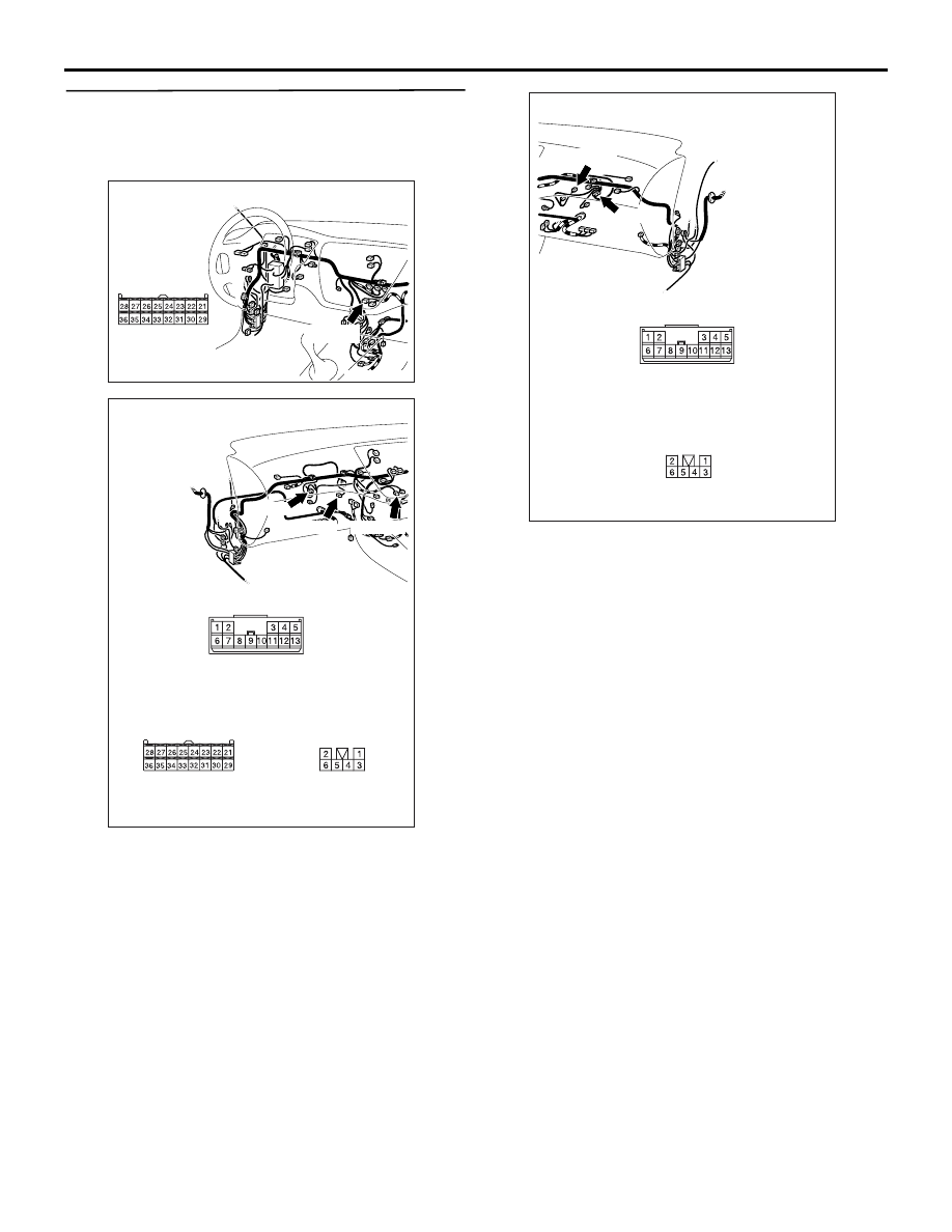
STEP 3. Check the wiring harness between C-37 
A/C-ECU connector (terminals 22 and 25) and 
C-144 air mixing damper control motor and 
potentiometer connector (terminals 3 and 1).

NOTE: Prior to the wiring harness inspection, check 
intermediate connector C-10, and repair if necessary.

• Check the motor activating lines for open or short 

circuit.

Q: Is the check result normal?

YES : 

Malfunction of the automatic A/C control 

panel (A/C-ECU)

NO : 

Repair the wiring harness.

AC504622AC

Connector: C-37 <LHD>

Harness side

C-37 (B)

AC504624AN

Connectors: C-10, C-37, C-144 <RHD>

Harness side

C-10

C-37

C-144

C-10

C-144

C-37 (B)

Harness side

AC504701AC

Connectors: C-10, C-144 <LHD>

Harness side

C-10

C-144

C-144

C-10

TROUBLESHOOTING

HEATER, AIR CONDITIONER AND VENTILATION

55-26

Code No.42: Mode Selection Damper Control Motor and Potentiometer Activating System

COMMENTS ON TROUBLE SYMPTOM

This code is set when the mode selection damper 
cannot be rotated to the preset opening angle.

PROBABLE CAUSES

• Malfunction of the mode selection damper control 

motor and potentiometer

• Malfunction of the automatic A/C control panel 

(A/C-ECU)

• Damaged the wiring harness or connectors

DIAGNOSIS PROCEDURE

STEP 1. Check the mode selection damper 
control motor and potentiometer.
Refer to 

P.55-114

.

Q: Is the check result normal?

YES : 

Go to Step 2.

NO : 

Replace the mode selection damper control 
motor and potentiometer.

Mode Selection Damper Control Motor and Potentiometer Circuit

Wire colour code
B : Black     LG : Light green     G : Green     L : Blue     W : White     Y : Yellow     SB : Sky blue
BR : Brown     O : Orange     GR : Grey     R : Red     P : Pink     V : Violet     PU : Purple

MOTOR
DRIVE CIRCUIT

A/C-ECU

MODE SELECTION DAMPER CONTROL
MOTOR AND POTENTIOMETER

TROUBLESHOOTING

HEATER, AIR CONDITIONER AND VENTILATION

55-27

STEP 2. Connector check: C-37 A/C-ECU 
connector and C-143 mode selection damper 
control motor and potentiometer connector

Q: Is the check result normal?

YES : 

Go to Step 3.

NO : 

Repair the connector.

AC504622AC

Connector: C-37 <LHD>

Harness side

C-37 (B)

AC504624AO

Connectors: C-37, C-143 <RHD>

Harness side

C-37

C-143

C-143

C-37 (B)

AC504617AM

Connector: C-143 <LHD>

Harness side

TROUBLESHOOTING

HEATER, AIR CONDITIONER AND VENTILATION

55-28

STEP 3. Check the wiring harness between C-37 
A/C-ECU connector (terminals 21 and 24) and 
C-143 mode selection damper control motor and 
potentiometer connector (terminals 3 and 1).

NOTE: Prior to the wiring harness inspection, check 
intermediate connector C-10, and repair if necessary.

• Check the motor activating lines for open or short 

circuit.

Q: Is the check result normal?

YES : 

Replace the automatic A/C control panel 

(A/C-ECU).

NO : 

Repair the wiring harness.

AC504622AC

Connector: C-37 <LHD>

Harness side

C-37 (B)

AC504624AP

Connectors: C-10, C-37, C-143 <RHD>

Harness side

C-10

C-37

C-143

C-10

C-143

C-37 (B)

Harness side

AC504701AD

Connectors: C-10, C-143 <LHD>

Harness side

C-10

C-143

C-10

C-143


Content   ..  536  537  538  539   ..