Mitsubishi Lancer Evolution IX. Manual - part 536
 

  Index      Mitsubishi     Mitsubishi Lancer Evolution IX - service repair manual


Search            


Content   ..  534  535  536  537   ..


Mitsubishi Lancer Evolution IX. Manual - part 536


TROUBLESHOOTING

HEATER, AIR CONDITIONER AND VENTILATION

55-17

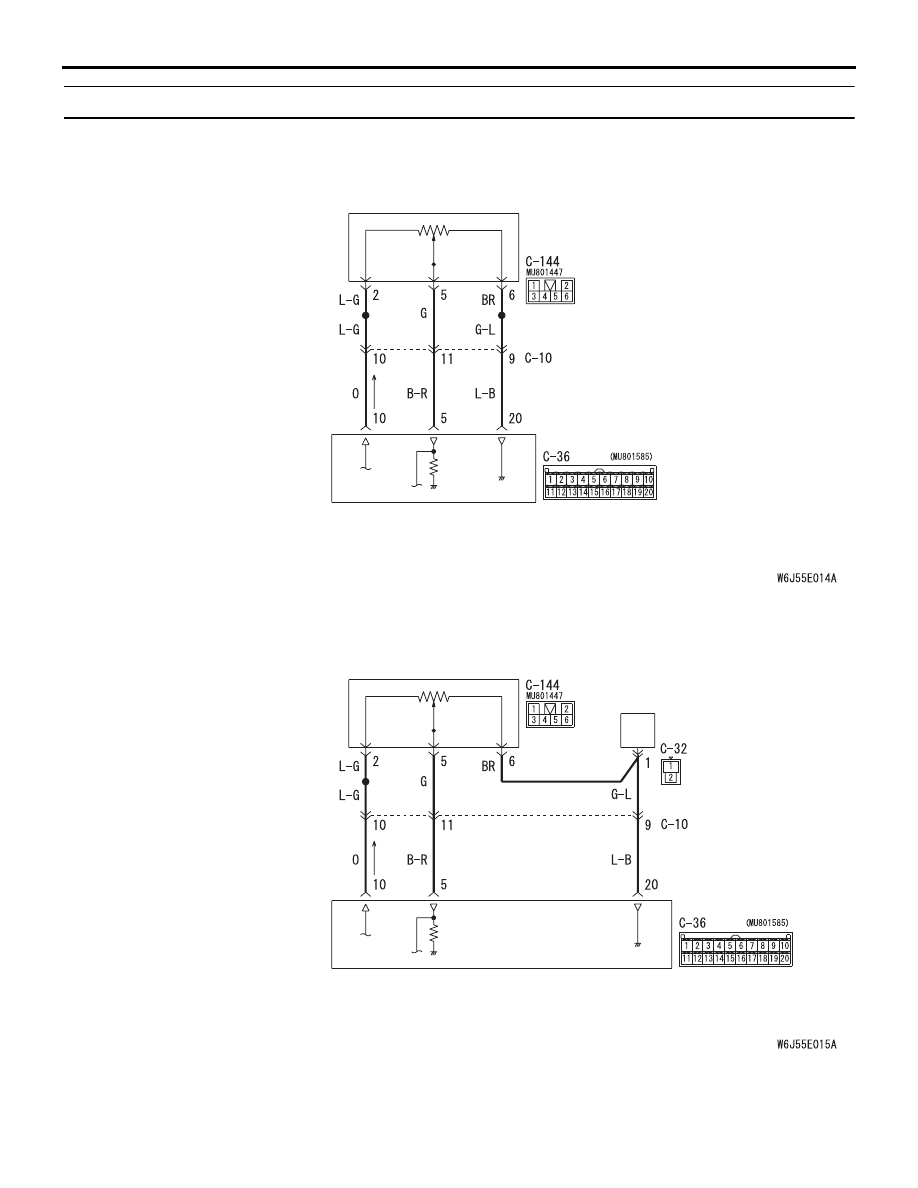
Code No.31: Air Mixing Damper Control Motor Potentiometer System

<LHD>

<RHD>

Air Mixing Damper Control Motor Potentiometer Circuit

Wire colour code
B : Black     LG : Light green     G : Green     L : Blue     W : White     Y : Yellow     SB : Sky blue
BR : Brown     O : Orange     GR : Grey     R : Red     P : Pink     V : Violet     PU : Purple

A/C-ECU

AIR MIXING DAMPER
CONTROL MOTOR AND
POTENTIOMETER

Air Mixing Damper Control Motor Potentiometer Circuit

Wire colour code
B : Black     LG : Light green     G : Green     L : Blue     W : White     Y : Yellow     SB : Sky blue
BR : Brown     O : Orange     GR : Grey     R : Red     P : Pink     V : Violet     PU : Purple

A/C-ECU

AIR MIXING DAMPER
CONTROL MOTOR AND
POTENTIOMETER

TROUBLESHOOTING

HEATER, AIR CONDITIONER AND VENTILATION

55-18

COMMENTS ON TROUBLE SYMPTOM

This code is set when the air mixing damper control 
motor potentiometer does not send any signal to the 
A/C-ECU due to short or open circuit.

PROBABLE CAUSES

• Malfunction of the air mixing damper control 

motor and potentiometer

• Damaged the wiring harness or connectors

• Malfunction of the automatic A/C control panel 

(A/C-ECU)

DIAGNOSIS PROCEDURE

STEP 1. Check the air mixing damper control 
motor and potentiometer.
Refer to 

P.55-114

.

Q: Is the check result normal?

YES : 

Go to Step 2.

NO : 

Replace the air mixing damper control 
motor and potentiometer.

STEP 2. Connector check: C-36 A/C-ECU 
connector and C-144 air mixing damper control 
motor and potentiometer connector

Q: Is the check result normal?

YES : 

Go to Step 3.

NO : 

Repair the connector.

AC504622AB

Connector: C-36 <LHD>

Harness side

C-36 (B)

AC504624AI

Connectors: C-36, C-144 <RHD>

Harness side

C-36

C-144

C-144

C-36 (B)

AC504617AL

Connector: C-144 <LHD>

Harness side

TROUBLESHOOTING

HEATER, AIR CONDITIONER AND VENTILATION

55-19

STEP 3. Check the wiring harness between C-36 
A/C-ECU connector (terminals 10, 5 and 20) and 
C-144 air mixing damper control motor and 
potentiometer connector (terminals 2, 5 and 6).

NOTE: Prior to the wiring harness inspection, check 
intermediate connector C-10, and heater water tem-
perature sensor connector C-32 <RH drive vehi-
cles>, and repair if necessary.

• Check the potentiometer power supply, earth and 

signal line for open or short circuit.

Q: Is the check result normal?

YES : 

Replace the automatic A/C control panel 

(A/C-ECU).

NO : 

Repair the wiring harness.

AC504622AB

Connector: C-36 <LHD>

Harness side

C-36 (B)

AC504624AQ

Connectors: C-10, C-32, C-36, C-144 <RHD>

Harness side

C-10

C-36

C-144

C-10

C-144

C-36 (B)

Harness side

C-32

C-32

Harness side

AC504701AC

Connectors: C-10, C-144 <LHD>

Harness side

C-10

C-144

C-144

C-10

TROUBLESHOOTING

HEATER, AIR CONDITIONER AND VENTILATION

55-20

Code No.32: Mode Selection Damper Control Motor Potentiometer System

<LHD>

<RHD>

Mode Selection Damper Control Motor Potentiometer Circuit

Wire colour code
B : Black     LG : Light green     G : Green     L : Blue     W : White     Y : Yellow     SB : Sky blue
BR : Brown     O : Orange     GR : Grey     R : Red     P : Pink     V : Violet     PU : Purple

MODE SELECTION
DAMPER CONTROL
MOTOR AND
POTENTIOMETER

A/C-ECU

Mode Selection Damper Control Motor Potentiometer Circuit

Wire colour code
B : Black     LG : Light green     G : Green     L : Blue     W : White     Y : Yellow     SB : Sky blue
BR : Brown     O : Orange     GR : Grey     R : Red     P : Pink     V : Violet     PU : Purple

HEATER WATER 
TEMPERATURE SENSOR

MODE SELECTION
DAMPER CONTROL
MOTOR AND
POTENTIOMETER

A/C-ECU


Content   ..  534  535  536  537   ..