Mitsubishi Lancer Evolution IX. Manual - part 525
 

  Index      Mitsubishi     Mitsubishi Lancer Evolution IX - service repair manual


Search            


Content   ..  523  524  525  526   ..


Mitsubishi Lancer Evolution IX. Manual - part 525


TROUBLESHOOTING

ANTI-SKID BRAKING SYSTEM (ABS)

35B-131

(3) Set M.U.T.-II/III to data reading mode for following 

item.

• Item No.37: Steering wheel sensor neutral 

position learning

OK: 

Q: Is the steering wheel sensor straight ahead 

position learning input normal?
YES : 

Go to Step 5. 

NO : 

Confirm the steering wheel sensor is 
correctly installed. Then go to Step 4.

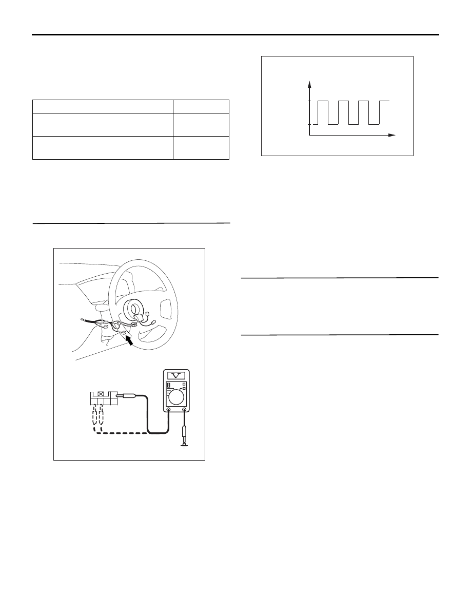
STEP 4. Check for steering wheel sensor output 
voltage.

(1) Connect steering wheel sensor connector C-230.

(2) Turn the ignition switch to the "ON" position.

(3) Measure the voltage, by backprobing, between 

terminal 1 and earth, terminal 4 and earth, and 
terminal 5 and earth. 

OK: The voltage should measure as indi-
cated in the figure.

Q: Is the steering wheel sensor output voltage 

normal?
YES : 

Go to Step 13.

NO : 

Replace the steering wheel sensor (Refer to 

P.35B-150

). and then go to Step 13.

STEP 5. Check the stop lamp.

Q: Does the stop lamp turn on and off normally?

YES : 

Go to Step 9.

NO : 

Go to Step 6.

STEP 6. Check the stop lamp switch installation 
condition.

Q: Is the stop lamp switch installed correctly?

YES : 

Check the stop lamp switch (Refer to 

GROUP 35A, Brake pedal 

P.35A-15

). Then 

go to Step 7.

NO : 

Repair the installation of the stop lamp 
switch (Refer to GROUP 35A, On-vehicle 
Service 

− Brake pedal Check and 

Adjustment 

P.35A-5

). Then go to Step 13.

Checking requirement

Display

After driving straight at vehicle 
speed over than 10 km/h

ON

Before driving with ignition switch 
ON

OFF

AC311195AD

Connector: C-230

Connector C-230
(Harness side)

5 4

1
2

3

AC211894

Time

AB

Voltage

2.7 - 4.4 V

0.8 - 2.1 V

Variations in voltage when turning the
steering wheel 

TROUBLESHOOTING

ANTI-SKID BRAKING SYSTEM (ABS)

35B-132

STEP 7. Check the following connectors.

Intermediate connectors C-129

Stop lamp switch connector C-102
Check the connectors for loose, corroded or dam-
aged terminals, or terminals pushed back in the con-
nector.

Q: Are the connectors and terminals in good 

condition?
YES : 

Go to Step 8.

NO : 

Repair it and then go to Step 13.

STEP 8. Check the following harness wires.

The wire between relay box in engine compartment 

(fuse No.10) and stop lamp switch connector 
C-102 (terminal 2)

• The wire between stop lamp switch connector 

C-102 (terminal 1) and stop lamps

Q: Is any harness wire damaged?

YES : 

Repair or replace it and then go to Step 13.

NO : 

Go to Step 9.

AC311160AG

Connector: C-129

18

3

16

15

14

1 2

17

4 5

8

20

19

6 7

2122

9 10

25

13

24

23

12

11

AC311161AI

Connector: C-102

4

1

2

3

AC208825AN

Fuse: No.10

No.10

AC311161AI

Connector: C-102

4

1

2

3

TROUBLESHOOTING

ANTI-SKID BRAKING SYSTEM (ABS)

35B-133

STEP 9. Check the stop lamp switch circuit. 
Voltage measurement at ABS-ECU connector 
B-118.

(1) Disconnect ABS-ECU connector B-118 and 

measure at the harness side.

(2) Depress the brake pedal to turn on the stop lamp 

switch.

(3) Measure the voltage between terminal 19 and 

earth.

OK: System voltage

Q: Is the check result normal?

YES : 

Go to Step 12.

NO : 

Go to Step 10.

STEP 10. Check the following connectors.

ABS-ECU connector B-118

Joint connector C-105

• Intermediate connector C-124

Stop lamp switch connector C-102

AC311168

28

32

34

12

11

33

30

21

9

10

22

31

7

8

29

20 19

24

2

26

4

5

6

27

18 17

3

25

16 15

1

23

13

14

Connector B-118
(harness side)

AG

B-118 (B)

Connector: B-118

AC311127AB

B-118 (B)

Connector: B-118

28

32

34

12

11

33

30

21

9

10

22

31

7

8

29

20 19

24

2

26

4

5

6

27

18 17

3

25

16 15

1

23

13

14

Harness side

AC311207AB

Connectors: C-105, C-124

C-105

C-124

33

22

11

28

17

16

15

14

13

12

25

2324

2627

3

1 2

4 5

21

20

19

18
2930

32

31

7

6

8

10

9

18

3

16

15

14

1 2

17

4 5

8

20

19

6 7

2122

9 10

25

13

24

23

12

11

Connector C-105

Connector C-124

AC311161AI

Connector: C-102

4

1

2

3

TROUBLESHOOTING

ANTI-SKID BRAKING SYSTEM (ABS)

35B-134

Check the connectors for loose, corroded or dam-
aged terminals, or terminals pushed back in the con-
nector.

Q: Are the connectors and terminals in good 

condition?
YES : 

Go to Step 11.

NO : 

Repair it and then go to Step 13.

STEP 11. Check the following harness wire.

The wire between stop lamp switch connector C-102 
(terminal 1) and ABS-ECU connector B-118 (terminal 
19)

Q: Is the harness wire damaged?

YES : 

Repair or replace it and then go to Step 13.

NO : 

Go to Step 13.

STEP 12. Check the following connector.

ABS-ECU connector B-118
Check the connector for loose, corroded or damaged 
terminals, or terminals pushed back in the connector.

Q: Are the connector and terminals in good 

condition?
YES : 

Replace the brake modulator hydraulic unit 

(integrated with ABS-ECU) (Refer to 

P.35B-143

). Then go to Step 13.

NO : 

Repair it and then go to Step 13.

STEP 13. Retest the system.

Q: Is the neutral position learning of the steering 

wheel sensor detected by the ABS system?
YES : 

The procedure is complete.

NO : 

Return to Step 1.

INSPECTION PROCEDURE 7: Faulty ABS Operation

COMMENT ON TROUBLE SYMPTOM 
(COMMENT)

The cause depends on driving and road surface con-
ditions, so diagnosis may be difficult. However, if no 
diagnosis code is set, carry out the following inspec-
tion.

PROBABLE CAUSES

The most likely cause for this case is:

• Malfunction of the brake modulator hydraulic unit

DIAGNOSIS

Check the brake modulator hydraulic unit (Refer to 

P.35B-140

). If the brake modulator hydraulic unit 

(integrated with ABS-ECU) is malfunctioning, replace 
it. Then check that the malfunction symptom is elimi-
nated.

AC311161AI

Connector: C-102

4

1

2

3

AC311127AB

B-118 (B)

Connector: B-118

28

32

34

12

11

33

30

21

9

10

22

31

7

8

29

20 19

24

2

26

4

5

6

27

18 17

3

25

16 15

1

23

13

14

Harness side

AC311127AB

B-118 (B)

Connector: B-118

28

32

34

12

11

33

30

21

9

10

22

31

7

8

29

20 19

24

2

26

4

5

6

27

18 17

3

25

16 15

1

23

13

14

Harness side


Content   ..  523  524  525  526   ..