Mitsubishi Lancer Evolution IX. Manual - part 524
 

  Index      Mitsubishi     Mitsubishi Lancer Evolution IX - service repair manual


Search            


Content   ..  522  523  524  525   ..


Mitsubishi Lancer Evolution IX. Manual - part 524


TROUBLESHOOTING

ANTI-SKID BRAKING SYSTEM (ABS)

35B-127

(2) Check for continuity between terminal 1 and 

earth with pulling or releasing the parking brake 
lever.

OK: If the parking brake lever is pulled, 
there should be no continuity, and if the 
parking brake lever is released, there 
should be continuity (less than 2 ohms).

Q: Does continuity exist when the parking brake lever 

is released, and dose continuity not exist when the 
parking brake lever is pulled?
YES : 

Go to Step 3.

NO : 

Go to Step 4.

STEP 3. Check the following connector.

ABS-ECU connector B-118
Check the connector for loose, corroded or damaged 
terminals, or terminals pushed back in the connector.

Q: Are the connector and terminals in good 

condition?
YES : 

Replace the brake modulator hydraulic unit 

(integrated with ABS-ECU) (Refer to 

P.35B-143

). Then go to Step 6.

NO : 

Go to Step 6.

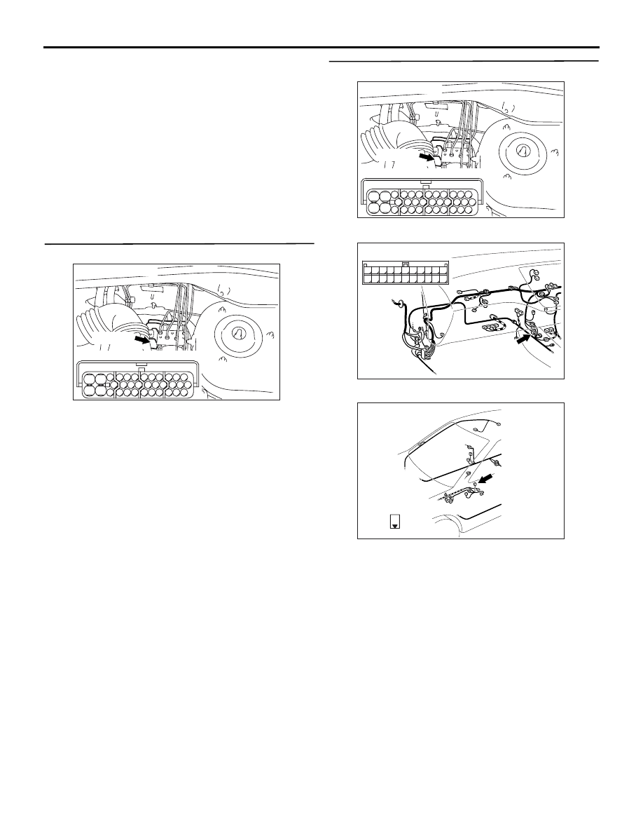
STEP 4. Check the following connectors.

ABS-ECU connector B-118

Intermediate connector C-122

Parking brake switch connector D-28
Check the connectors for loose, corroded or dam-
aged terminals, or terminals pushed back in the con-
nector.

Q: Are the connectors and terminals in good 

condition?
YES : 

Go to Step 5.

NO : 

Repair it and then go to Step 6.

AC311127AB

B-118 (B)

Connector: B-118

28

32

34

12

11

33

30

21

9

10

22

31

7

8

29

20 19

24

2

26

4

5

6

27

18 17

3

25

16 15

1

23

13

14

Harness side

AC311127AB

B-118 (B)

Connector: B-118

28

32

34

12

11

33

30

21

9

10

22

31

7

8

29

20 19

24

2

26

4

5

6

27

18 17

3

25

16 15

1

23

13

14

Harness side

AC311160AC

Connector: C-122

C-122 (L)

2

1

3

13

12

14

21

10

5

4

6

16

15

17

7 8 9

19

18

20

11

22

AC311162AC

Connector: D-28

D-28 (B)

1

Harness side

TROUBLESHOOTING

ANTI-SKID BRAKING SYSTEM (ABS)

35B-128

STEP 5. Check the following harness wire.

The wire between parking brake switch connector 
D-28 (terminal 1) and ABS-ECU connector B-118 
(terminal 1)

Q: Is the harness wire damaged?

YES : 

Repair or replace it and then go to Step 6.

NO : 

Replace the parking brake switch (Refer to 
GROUP 36, Parking Brake Lever 

P.36-4

). 

Then go to Step 6.

STEP 6. Check whether the diagnosis code is 
reset.

Q: Does the parking brake switch turn ON/OFF 

normally in the inspection by M.U.T.-II/III data list?
YES : 

The procedure is complete.

NO : 

Return to Step 1.

AC311162AC

Connector: D-28

D-28 (B)

1

Harness side

AC311127AB

B-118 (B)

Connector: B-118

28

32

34

12

11

33

30

21

9

10

22

31

7

8

29

20 19

24

2

26

4

5

6

27

18 17

3

25

16 15

1

23

13

14

Harness side

TROUBLESHOOTING

ANTI-SKID BRAKING SYSTEM (ABS)

35B-129

INSPECTION PROCEDURE 6: The Neutral Position Learning of the Steering Wheel Sensor is not 
Detected.

CIRCUIT OPERATION

The ABS system detects the neutral position learning 
of the steering wheel sensor by the signal from the 
stop lamp.

COMMENT ON TROUBLE SYMPTOM

The diagnosis is difficult because it depends on driv-
ing condition and road surface, if the diagnosis code 
has not been set, carry out the following checks 
(refer to TROUBLESHOOTING HINTS).

IGNITION
SWITCH (IG2)

STEERING
WHEEL
SENSOR

ABS-ECU

Wire colour code
B : Black     LG : Light green
G : Green     L : Blue
W : White     Y : Yellow
SB : Sky blue     BR : Brown
O : Orange     GR : Gray
R : Red     P : Pink     V : Violet

ST-1

ST-2

ST-N

Steering Wheel Sensor Circuit

TROUBLESHOOTING

ANTI-SKID BRAKING SYSTEM (ABS)

35B-130

PROBABLE CAUSES

The most likely causes for this case are:

• Damaged wiring harness or connector

• Malfunction of the stop lamp switch system

• Tyres are not all the same diameter

• Malfunction of suspension

• Malfunction of the steering wheel sensor installa-

tion

• Malfunction of the brake modulator hydraulic unit 

(integrated with ABS-ECU)

DIAGNOSIS

STEP 1. Check the front tyres.

Q: Are the tyre diameters different?

YES : 

Replace the appropriate tyre and then go to 

Step 13.

NO : 

Go to Step 2.

STEP 2. Check the front suspension.

Q: Is the front suspension abnormal?

YES : 

Repair the front suspension and then go to 

Step 13.

NO : 

Go to Step 3.

STEP 3. M.U.T.-II/III data list.

CAUTION

To prevent damage to M.U.T.-II/III, always turn the 
ignition switch to the "LOOK" (OFF) position 
before connecting or disconnecting M.U.T.-II/III.

(1) Connect M.U.T.-II/III as shown in the illustration.
(2) Start the engine.

AC311157

Steering shaft

AB

MB991502

<Using the M.U.T.-II>

AC311153

AB

MB991911

16-PIN

MB991827

MB991824 

<Using the M.U.T.-III>


Content   ..  522  523  524  525   ..